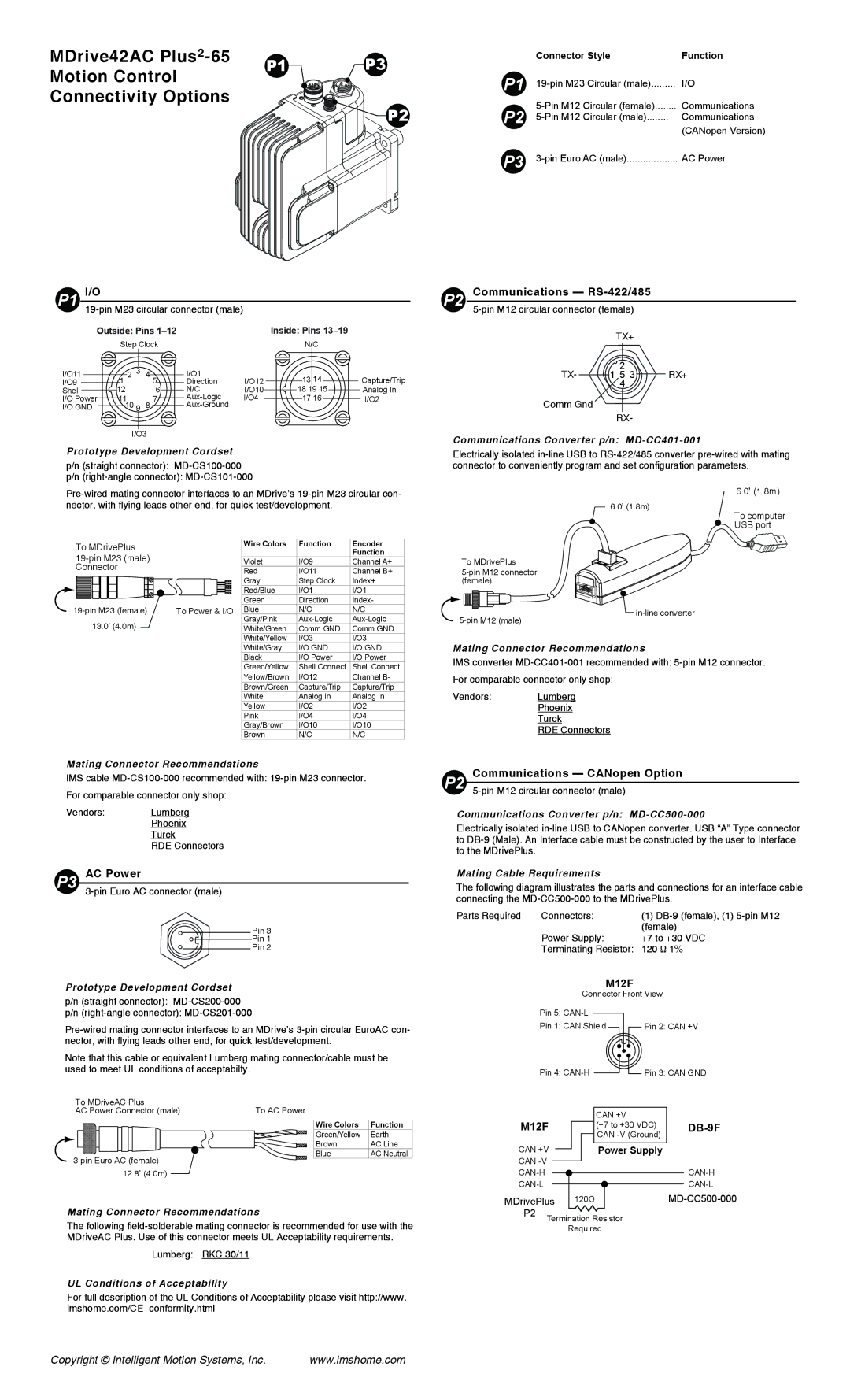
MDrive42AC | P1 | P3 | |
Motion Control | |||
|
|
Connectivity Options
P2
P1 | I/O |
|
|
|
|
|
|
|
|
|
|
|
| ||||||
| Outside: Pins |
|
| Inside: Pins |
| ||||
|
| Step Clock |
|
| N/C |
| |||
I/O11 |
| 1 | 2 3 | 4 | 5 | I/O1 | I/O12 | 13 14 | Capture/Trip |
I/O9 |
|
|
| Direction | |||||
Shell |
| 12 |
|
| 6 | N/C | I/O10 | 18 19 15 | Analog In |
I/O Power | 11 |
|
| 7 | I/O4 | 17 16 | I/O2 | ||
I/O GND | 10 9 | 8 |
|
|
|
| |||
I/O3
Prototype Development Cordset
p/n (straight connector):
p/n
| Connector Style | Function | |
P1 | I/O | ||
P2 | Circular (female) | Communications | |
Circular (male) | Communications | ||
|
|
| (CANopen Version) |
P3 | AC Power | ||
P2 Communications — RS-422/485
TX+
2
TX- 1 5 3 RX+ 4
Comm Gnd
RX-
Communications Converter p/n: MD-CC401-001
Electrically isolated
To MDrivePlus |
|
|
|
| Wire Colors | Function | Encoder | |||||||
|
|
|
|
|
| Function | ||||||||
|
|
|
|
|
| |||||||||
|
|
|
| Violet | I/O9 | Channel A+ | ||||||||
Connector |
|
|
|
| ||||||||||
|
|
|
| Red | I/O11 | Channel B+ | ||||||||
|
|
|
|
|
|
|
|
|
|
|
| |||
|
|
|
|
|
|
|
|
|
|
|
| Gray | Step Clock | Index+ |
|
|
|
|
|
|
|
|
|
|
|
| Red/Blue | I/O1 | I/O1 |
|
|
|
|
|
|
|
|
|
|
|
| |||
|
|
|
|
|
|
|
|
|
|
|
| Green | Direction | Index- |
|
|
|
|
|
|
|
|
|
|
|
| |||
To Power & I/O | Blue | N/C | N/C | |||||||||||
|
| 13.0’ (4.0m) |
|
|
|
| Gray/Pink | |||||||
|
|
|
|
|
| White/Green | Comm GND | Comm GND | ||||||
|
|
|
|
|
|
|
|
|
|
|
| White/Yellow | I/O3 | I/O3 |
To MDrivePlus
6.0’ (1.8m)
6.0’ (1.8m)
To computer
USB port

in-line converter
White/Gray | I/O GND | I/O GND |
Black | I/O Power | I/O Power |
Green/Yellow | Shell Connect | Shell Connect |
Yellow/Brown | I/O12 | Channel B- |
Brown/Green | Capture/Trip | Capture/Trip |
White | Analog In | Analog In |
Yellow | I/O2 | I/O2 |
Pink | I/O4 | I/O4 |
Gray/Brown | I/O10 | I/O10 |
Brown | N/C | N/C |
Mating Connector Recommendations
IMS cable
Vendors: Lumberg
Phoenix
Turck
RDE Connectors
P3 AC Power
Pin 3
Pin 1
Pin 2
Prototype Development Cordset
p/n (straight connector):
p/n
Note that this cable or equivalent Lumberg mating connector/cable must be used to meet UL conditions of acceptabilty.
To MDriveAC Plus |
|
|
AC Power Connector (male) | To AC Power |
|
| Wire Colors | Function |
| Green/Yellow | Earth |
| Brown | AC Line |
Blue | AC Neutral | |
|
| |
12.8’ (4.0m) |
|
|
Mating Connector Recommendations
The following
Lumberg: RKC 30/11
UL Conditions of Acceptability
For full description of the UL Conditions of Acceptability please visit http://www. imshome.com/CE_conformity.html
Mating Connector Recommendations
IMS converter
Vendors: Lumberg
Phoenix
Turck
RDE Connectors
Communications — CANopen Option
P2
Communications Converter p/n: MD-CC500-000
Electrically isolated
Mating Cable Requirements
The following diagram illustrates the parts and connections for an interface cable connecting the
Parts Required | Connectors: | (1) |
|
| (female) |
| Power Supply: | +7 to +30 VDC |
| Terminating Resistor: | 120 Ω 1% |
M12F
|
|
|
|
|
| Connector Front View |
|
| ||||||||
| Pin 5: |
|
|
|
|
|
|
|
|
|
| |||||
|
|
|
|
|
|
|
|
|
|
| ||||||
| Pin 1: CAN Shield |
|
|
|
| Pin 2: CAN +V | ||||||||||
| Pin 4: |
|
|
|
|
|
|
| Pin 3: CAN GND | |||||||
|
|
|
|
|
|
|
| |||||||||
|
|
|
|
|
|
|
| |||||||||
|
|
|
|
|
|
|
| |||||||||
|
|
|
|
|
|
|
| |||||||||
|
|
|
|
|
|
|
|
|
|
|
| |||||
M12F |
|
|
| CAN +V |
|
|
|
| ||||||||
|
|
| (+7 to +30 VDC) |
|
| |||||||||||
CAN +V |
|
|
| CAN |
|
| ||||||||||
|
|
|
|
| ||||||||||||
|
|
| Power Supply |
|
| |||||||||||
|
|
|
|
| ||||||||||||
CAN |
|
|
|
|
|
|
|
|
|
|
|
|
| |||
|
|
|
|
|
|
|
|
|
|
|
|
| ||||
|
|
|
|
|
|
|
|
|
|
|
|
|
| |||
|
|
|
|
|
|
|
|
|
|
|
|
|
| |||
|
|
|
|
|
|
|
|
|
|
|
|
|
| |||
|
|
|
|
|
|
|
|
|
|
|
|
|
| |||
MDrivePlus |
| 120Ω |
|
|
|
|
|
|
|
| ||||||
P2 |
|
|
|
|
|
|
|
|
|
|
|
|
|
|
|
|
Termination Resistor |
|
|
|
| ||||||||||||
|
|
|
|
| ||||||||||||
|
|
|
| Required |
|
|
|
| ||||||||
Copyright © Intelligent Motion Systems, Inc. | www.imshome.com |