ADJUSTING THE PATIENT OPERATED WHEEL LOCKS (FIGURE 2)
NOTE: Refer to INSTALLATION WARNINGS in the SAFETY SUMMARY in this instruction sheet.
NOTE: If wheels are pneumatic, before adjusting or replacing the wheel lock assemblies, ensure that the tires are inflated to the recommended psi on the side wall of tire. The recommended tire pressure is located on the side wall of the tire.
1.Loosen the bolt and locknut that secure the wheel lock assembly to the wheelchair frame.
2.Adjust the position of wheel lock until the mea- surement between the rear wheel and the wheel lock shoe is between 5/32 and
3.Securely tighten the bolt and locknut.
4.Engage wheel lock and ensure the wheelchair holds its position.
5.Repeat the above procedures until the wheel lock holds the wheelchair.
6.Repeat STEPS
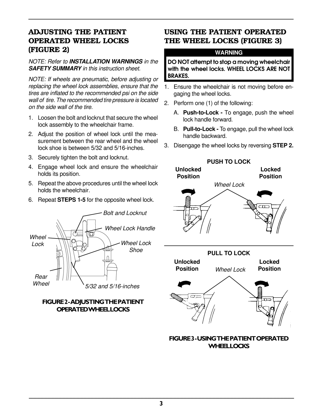
| Bolt and Locknut |
| Wheel Lock Handle |
Wheel | Wheel Lock |
Lock | |
| Shoe |
Rear |
|
Wheel | 5/32 and |
|
USING THE PATIENT OPERATED THE WHEEL LOCKS (FIGURE 3)
WARNING
DO NOT attempt to stop a moving wheelchair with the wheel locks. WHEEL LOCKS ARE NOT BRAKES.
1.Ensure the wheelchair is not moving before en- gaging the wheel locks.
2.Perform one (1) of the following:
A.
B.
3.Disengage the wheel locks by reversing STEP 2.
| PUSH TO LOCK |
Unlocked | Locked |
Position | Position |
| Wheel Lock |
| PULL TO LOCK |
|
Unlocked |
| Locked |
Position | Wheel Lock | Position |
FIGURE2-ADJUSTINGTHEPATIENT
OPERATEDWHEELLOCKS
FIGURE3-USINGTHEPATIENTOPERATED
WHEELLOCKS
3