PATIENT LIFT


CAMLOCK UPGRADE KIT

Installation, Assembly

1052250

and Operating Instructions


SAFETY SUMMARY

The following recommendations are made for the safe installation of the Patient Lift Camlock Upgrade Kit.

WARNING

Check ALL parts for shipping damage and test be- fore using. In case of damage, DO NOT use. Con- tact the carrier/dealer for further instructions.

Make certain all screws and nuts are tight at all times.

Kit Includes the following:

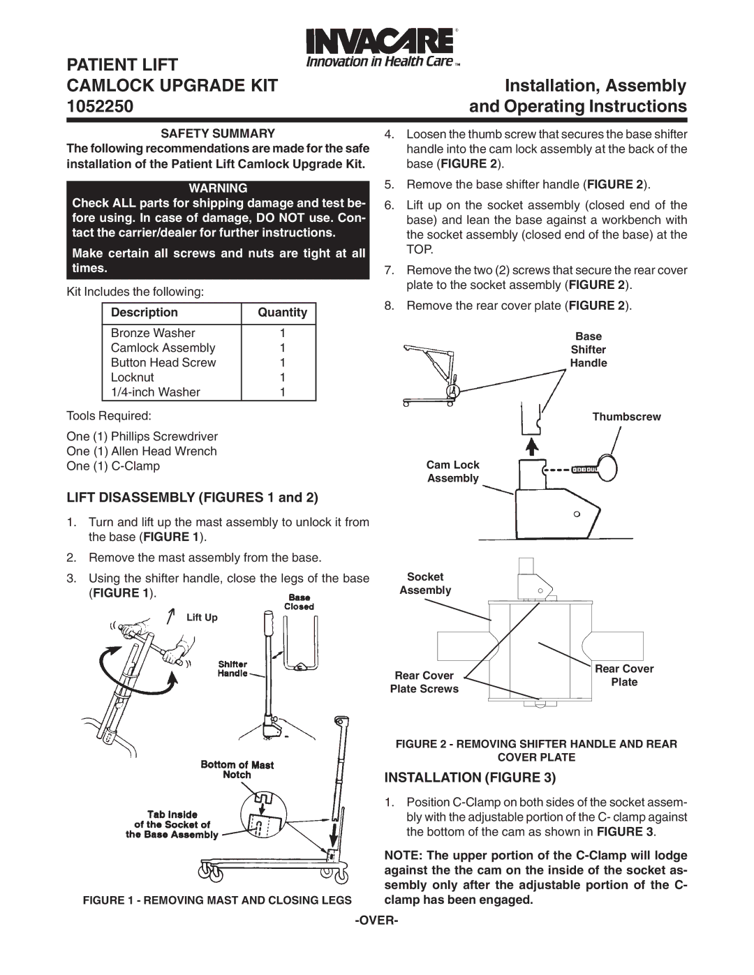
4.Loosen the thumb screw that secures the base shifter handle into the cam lock assembly at the back of the base (FIGURE 2).

5.Remove the base shifter handle (FIGURE 2).

6.Lift up on the socket assembly (closed end of the base) and lean the base against a workbench with the socket assembly (closed end of the base) at the TOP.

7.Remove the two (2) screws that secure the rear cover plate to the socket assembly (FIGURE 2).

Description

Quantity


Bronze Washer

1

Camlock Assembly

1

Button Head Screw

1

Locknut

1

1/4-inch Washer

1

Tools Required:

One (1) Phillips Screwdriver

One (1) Allen Head Wrench

One (1) C-Clamp

LIFT DISASSEMBLY (FIGURES 1 and 2)

1.Turn and lift up the mast assembly to unlock it from the base (FIGURE 1).

2.Remove the mast assembly from the base.

3.Using the shifter handle, close the legs of the base (FIGURE 1).

Lift Up

8. Remove the rear cover plate (FIGURE 2).

Base

Shifter

Handle

Thumbscrew

Cam Lock

Assembly

Socket

Assembly


Rear Cover


Rear Cover


Plate

Plate Screws


FIGURE 2 - REMOVING SHIFTER HANDLE AND REAR


COVER PLATE


INSTALLATION (FIGURE 3)


1. Position C-Clamp on both sides of the socket assem-


bly with the adjustable portion of the C- clamp against


the bottom of the cam as shown in FIGURE 3.


NOTE: The upper portion of the C-Clamp will lodge


against the the cam on the inside of the socket as-


sembly only after the adjustable portion of the C-

FIGURE 1 - REMOVING MAST AND CLOSING LEGS

clamp has been engaged.


-OVER-

Page 1
Image 1
Invacare 1052250 operating instructions Lift Disassembly Figures 1, Safety Summary, Over

1052250 specifications

The Invacare 1052250 is a cutting-edge mobility solution designed for individuals requiring assistance in their daily activities. Combining advanced technologies with user-friendly features, this product aims to enhance independence and improve the quality of life for its users.

One of the standout features of the Invacare 1052250 is its robust construction, ensuring durability while remaining lightweight. This makes it easy to maneuver both indoors and outdoors, providing users with the freedom to navigate their environment comfortably. The frame is crafted from high-grade aluminum, contributing to its strength without sacrificing portability.

Equipped with modern technologies, the Invacare 1052250 is designed for exceptional ease of use. Its innovative folding mechanism allows for quick and effortless storage or transport, making it ideal for users who are always on the move. The design incorporates a secure locking system, ensuring that the unit remains stable when in use.

Another notable aspect of the Invacare 1052250 is its ergonomic design. The chair features adjustable armrests and footrests, catering to the individual needs of each user. This adjustability allows for a customized fit, promoting comfort and reducing the risk of pressure ulcers during prolonged use.

The product includes a padded seat and backrest, designed for maximum comfort over extended periods. The fabric used in the upholstery is breathable, moisture-wicking, and easy to clean, making maintenance simple and straightforward. This attention to comfort and hygiene is particularly important for users who may spend significant amounts of time in their mobility devices.

Safety is paramount in the design of the Invacare 1052250. It features anti-tip wheels, ensuring stability on various terrains, and its braking system is responsive and straightforward, providing peace of mind when navigating slopes or uneven surfaces.

In summary, the Invacare 1052250 blends durability, comfort, and advanced technology to create a mobility solution that emphasizes user independence. With its lightweight construction, ergonomic features, and focus on safety, it stands out as an exemplary choice for those in need of assisted mobility. Whether for daily activities or occasional outings, this device is engineered to meet a diverse range of user needs, enhancing overall mobility and enhancing life quality.