8.Measure the distance between the bottom of the anti‐tipper wheels and the ground/floor.
•Non‐Adjustable Height Anti‐Tipper Assemblies: If the distance between the bottom of the anti‐tipper wheels and the ground/floor is not 1½ to 2‐inches, call Invacare Technical Support at the number listed on the back page.
•Adjustable Height Anti‐Tipper Assemblies: If the distance between the bottom of anti‐tipper wheels and the ground/floor is not 1½ to 2‐inches, adjust anti‐tippers. Refer to Adjusting Anti‐Tippers on page 3.
*NOTE: Non‐adjustable | Lower | Locking Hole | ||
(STEPS 2,3) | ||||
anti‐tipper shown. | Frame | |||
(if provided) | Tube |
| ||
|
| |||
| (STEP 4) |
| ||
|
|
| ||
|
| (STEP 3) |
| Plug Button or End | |
Spring Button(s) | Cap (End cap not | |
shown) (STEP 1) | ||
(STEP 5) | ||
|
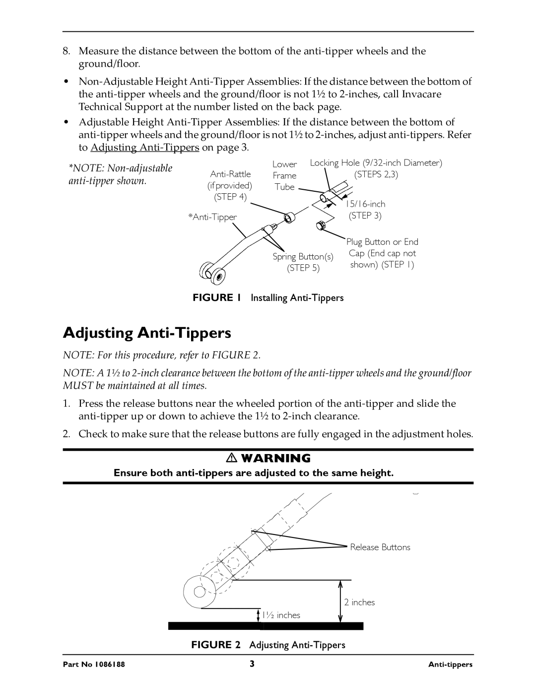
FIGURE 1 Installing Anti-Tippers
Adjusting Anti-Tippers
NOTE: For this procedure, refer to FIGURE 2.
NOTE: A 1½ to 2‐inch clearance between the bottom of the anti‐tipper wheels and the ground/floor MUST be maintained at all times.
1.Press the release buttons near the wheeled portion of the anti‐tipper and slide the anti‐tipper up or down to achieve the 1½ to 2‐inch clearance.
2.Check to make sure that the release buttons are fully engaged in the adjustment holes.
WARNING
Ensure both anti-tippers are adjusted to the same height.
![]()
![]() Release Buttons
Release Buttons
![]() 1½ inches
1½ inches
2 inches
FIGURE 2 Adjusting Anti-Tippers
Part No 1086188 | 3 |
