3. Determine an acceptable mounting location for the
NOTE: The location depends on the wheelchair model. The
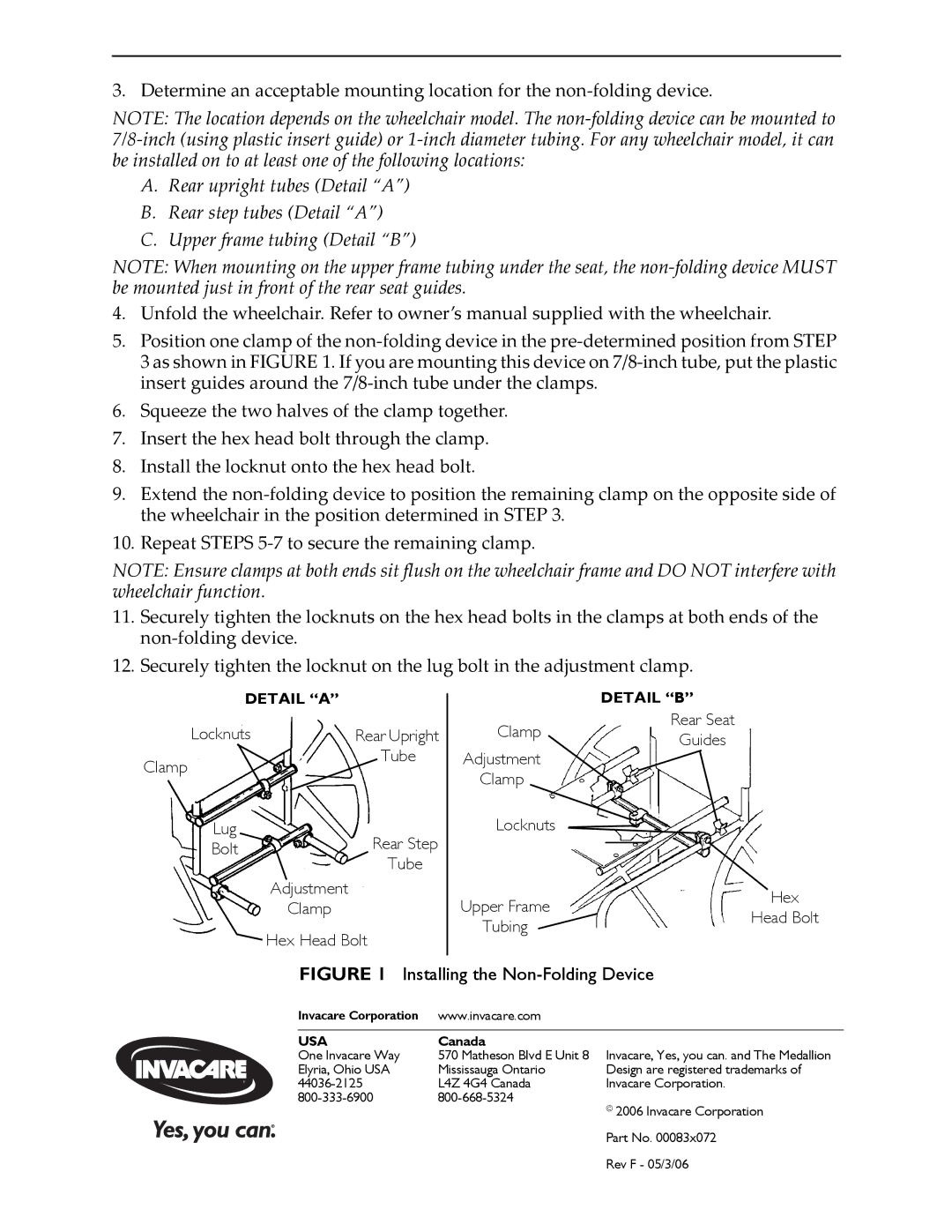
A.Rear upright tubes (Detail “A”)
B.Rear step tubes (Detail “A”)
C.Upper frame tubing (Detail “B”)
NOTE: When mounting on the upper frame tubing under the seat, the
4.Unfold the wheelchair. Refer to owner’s manual supplied with the wheelchair.
5.Position one clamp of the
6.Squeeze the two halves of the clamp together.
7.Insert the hex head bolt through the clamp.
8.Install the locknut onto the hex head bolt.
9.Extend the
10.Repeat STEPS
NOTE: Ensure clamps at both ends sit flush on the wheelchair frame and DO NOT interfere with wheelchair function.
11.Securely tighten the locknuts on the hex head bolts in the clamps at both ends of the
12.Securely tighten the locknut on the lug bolt in the adjustment clamp.
DETAIL “A” |
|
Locknuts | Rear Upright |
Clamp | Tube |
|
Lug
Bolt 
 Rear Step
Tube
Adjustment
Clamp

 Hex Head Bolt
DETAIL “B”
Clamp | Rear Seat | |
Guides | ||
Adjustment | ||
| ||
Clamp |
| |
Locknuts |
| |
Upper Frame | Hex | |
Head Bolt | ||
Tubing | ||
|
FIGURE 1 Installing the Non-Folding Device
Invacare Corporation | www.invacare.com |
|
|
|
|
USA | Canada |
|
One Invacare Way | 570 Matheson Blvd E Unit 8 Invacare, Yes, you can. and The Medallion | |
Elyria, Ohio USA | Mississauga Ontario | Design are registered trademarks of |
L4Z 4G4 Canada | Invacare Corporation. | |
| ||
©2006 Invacare Corporation
Part No. 00083x072
Rev F - 05/3/06