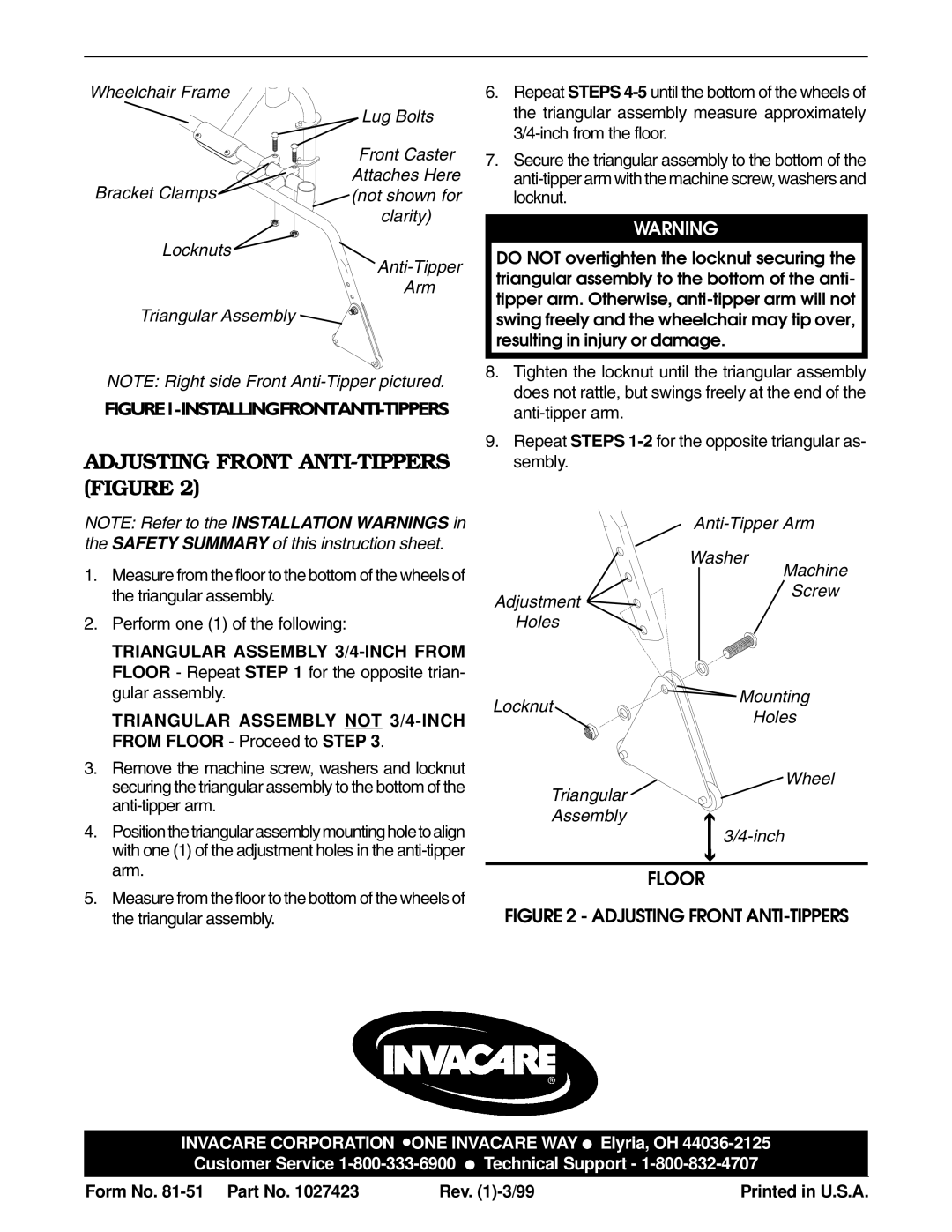
Wheelchair Frame
Lug Bolts
Front Caster
Attaches Here
Bracket Clamps(not shown for clarity)
Locknuts
Arm
Triangular Assembly
NOTE: Right side Front
FIGURE1-INSTALLINGFRONTANTI-TIPPERS
ADJUSTING FRONT ANTI-TIPPERS (FIGURE 2)
6.Repeat STEPS
7.Secure the triangular assembly to the bottom of the
WARNING
DO NOT overtighten the locknut securing the triangular assembly to the bottom of the anti- tipper arm. Otherwise,
8.Tighten the locknut until the triangular assembly does not rattle, but swings freely at the end of the
9.Repeat STEPS
NOTE: Refer to the INSTALLATION WARNINGS in the SAFETY SUMMARY of this instruction sheet.
1. Measure from the floor to the bottom of the wheels of |
Washer
Machine
the triangular assembly. |
2. Perform one (1) of the following: |
TRIANGULAR ASSEMBLY |
FLOOR - Repeat STEP 1 for the opposite trian- |
Adjustment
Holes
Screw
| gular assembly. |
| TRIANGULAR ASSEMBLY NOT |
| FROM FLOOR - Proceed to STEP 3. |
3. | Remove the machine screw, washers and locknut |
| securing the triangular assembly to the bottom of the |
|
|
4. | Position the triangular assembly mounting hole to align |
| with one (1) of the adjustment holes in the |
| arm. |
5. | Measure from the floor to the bottom of the wheels of |
| the triangular assembly. |
Mounting
Locknut
Holes
Wheel
Triangular
Assemblyé
ê
FLOOR
FIGURE 2 - ADJUSTING FRONT ANTI-TIPPERS
INVACARE CORPORATION ![]() ONE INVACARE WAY ● Elyria, OH
ONE INVACARE WAY ● Elyria, OH
Form No. | Rev. | Printed in U.S.A. |