Invacare 9000 instruction sheet Installing ANTI-TIPPERS Figure

Models: 9000

1 4
Download 4 pages 10.48 Kb
Page 2
Image 2

INSTALLING ANTI-TIPPERS (FIGURE 1)

1.Remove plug button (not shown) from end of rear frame tubing and install anti-rattles if not already installed.

2.Press the release buttons IN and insert the anti-tippers with the anti-tipper wheels pointing toward the ground/floor into the rear frame tubing until the bottom release button locks in place.

3.Measure the distance between the bottom of the
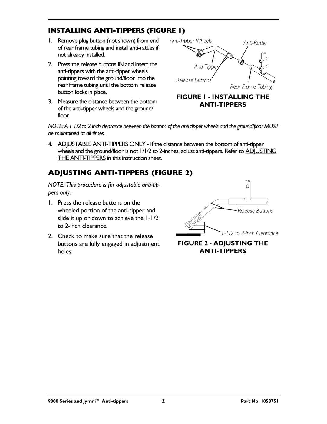
 anti-tipper wheels and the ground/ floor.

Anti-Tipper Wheels

Anti-Rattle


Anti-Tipper

Release Buttons Rear Frame Tubing

FIGURE 1 - INSTALLING THE

ANTI-TIPPERS

NOTE: A 1-1/2 to 2-inch clearance between the bottom of the anti-tipper wheels and the ground/floor MUST be maintained at all times.

4.ADJUSTABLE ANTI-TIPPERS ONLY - If the distance between the bottom of anti-tipper wheels and the ground/floor is not 1/1/2 to 2-inches, adjust anti-tippers. Refer to ADJUSTING THE ANTI-TIPPERS in this instruction sheet.

ADJUSTING ANTI-TIPPERS (FIGURE 2)

NOTE: This procedure is for adjustable anti-tip- pers only.

1.Press the release buttons on the wheeled portion of the anti-tipper and slide it up or down to achieve the 1-1/2 to 2-inch clearance.

2.Check to make sure that the release buttons are fully engaged in adjustment holes.

Release Buttons

1-1/2 to 2-inch Clearance

FIGURE 2 - ADJUSTING THE

ANTI-TIPPERS

9000 Series and Jymni™ Anti-tippers

2

Part No. 1058751

Page 2
Image 2
Invacare 9000 instruction sheet Installing ANTI-TIPPERS Figure