Personal |
|
| PERSONAL |
|
| BACK | |
Back | Mounting |
| |
|
| ||
(Inside) | Holes |
|
|
2 | 1 | 3 |
|
|
|
| |
|
| A | A |
|
|
| SECTION |
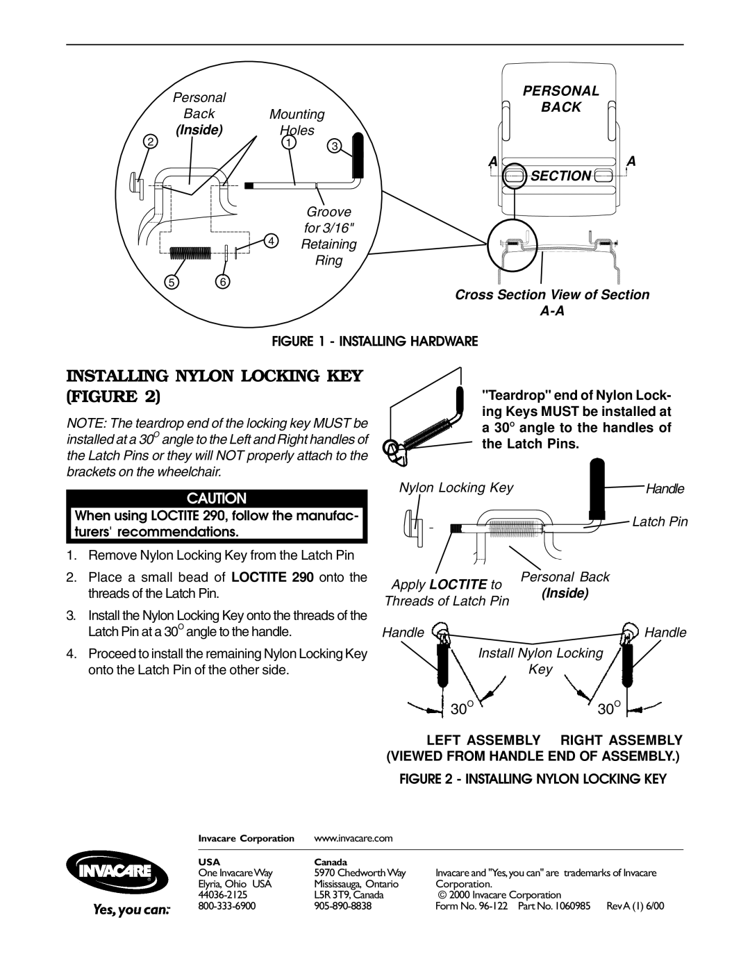
Groove for 3/16"
4 Retaining Ring
5 6
Cross Section View of Section
FIGURE 1 - INSTALLING HARDWARE
INSTALLING NYLON LOCKING KEY (FIGURE 2)
NOTE: The teardrop end of the locking key MUST be installed at a 30O angle to the Left and Right handles of the Latch Pins or they will NOT properly attach to the brackets on the wheelchair.
CAUTION
When using LOCTITE 290, follow the manufac- turers' recommendations.
1.Remove Nylon Locking Key from the Latch Pin
2.Place a small bead of LOCTITE 290 onto the threads of the Latch Pin.
3.Install the Nylon Locking Key onto the threads of the Latch Pin at a 30O angle to the handle.
4.Proceed to install the remaining Nylon Locking Key onto the Latch Pin of the other side.
"Teardrop" end of Nylon Lock- ing Keys MUST be installed at a 30O angle to the handles of the Latch Pins.
Nylon Locking Key | Handle |
Latch Pin
Personal Back
Apply LOCTITE to
(Inside)
Threads of Latch Pin
HandleHandle
Install Nylon Locking
Key
30O30O
LEFT ASSEMBLY RIGHT ASSEMBLY (VIEWED FROM HANDLE END OF ASSEMBLY.)
FIGURE 2 - INSTALLING NYLON LOCKING KEY
Invacare Corporation | www.invacare.com |
|
|
|
|
USA | Canada |
|
One InvacareWay | 5970 Chedworth Way | Invacare and "Yes,you can" are trademarks of Invacare |
Elyria, Ohio USA | Mississauga, Ontario | Corporation. |
L5R 3T9, Canada | © 2000 Invacare Corporation | |
Form No. |