PADDED ACTUATOR COVER
PART NO. 1083039
Assembly, Installation and Operating Instructions
NOTE: Check all parts for shipping damage. In case of dam- age, DO NOT use. Contact your Dealer for further instruction.
SAFETY SUMMARY
The following recommendations are made for the safe use of the PADDED ACTUATOR COVER:
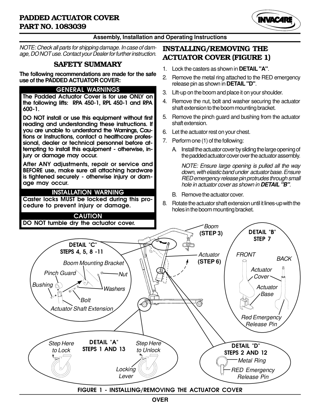
INSTALLING/REMOVING THE ACTUATOR COVER (FIGURE 1)
1.Lock the casters as shown in DETAIL "A".
2.Remove the metal ring attached to the RED emergency release pin as shown in DETAIL "D".
GENERAL WARNINGS
The Padded Actuator Cover is for use ONLY on the following lifts: RPA
DO NOT install or use this equipment without first reading and understanding these instructions. If you are unable to understand the Warnings, Cau- tions or Instructions, contact a healthcare profes- sional, dealer or technical personnel before at- tempting to install this equipment - otherwise, in- jury or damage may occur.
After ANY adjustments, repair or service and BEFORE use, make sure all attaching hardware is tightened securely - otherwise injury or dam- age may occur.
INSTALLATION WARNING
Caster locks MUST be locked during this pro- cedure to prevent injury or damage.
CAUTION
DO NOT tumble dry the actuator cover.
DETAIL "C"
STEPS 4, 5, 8 | |
Boom Mounting Bracket | |
Pinch Guard | Nut |
Bushing | Washers |
ê | |
ê |
|
| Bolt |
Actuator Shaft Extension | |
3.Lift-up on the boom and place it on your shoulder.
4.Remove the nut, bolt and washer securing the actuator shaft extension to the boom mounting bracket.
5.Remove the pinch guard and bushing from the actuator shaft extension.
6.Let the actuator rest on your chest.
7.Perform one (1) of the following:
A.Install the actuator cover by sliding the large opening of the padded actuator cover over the actuator assembly.
NOTE: Ensure large opening is pulled all the way down, with elastic band under actuator base. Ensure RED emergency release pin protrudes through small hole in actuator cover as shown in DETAIL "B".
B.Remove the actuator cover.
8.Rotate the actuator shaft extension until it
Boom | DETAIL "B" |
(STEP 3) | |
| STEP 7 |
Actuator | FRONT |
(STEP 6) | BACK |
| |
| Actuator |
| Cover |
| Actuator |
| Base |
| Red Emergency |
| Release Pin |
Step Here | DETAIL "A" | Step Here |
to Lock | STEPS 1 AND 13 | to Unlock |
Locking
Lever
 DETAIL "D" STEPS 2 AND 12
Metal Ring
![]()
![]()
![]() RED Emergency
RED Emergency
Release Pin