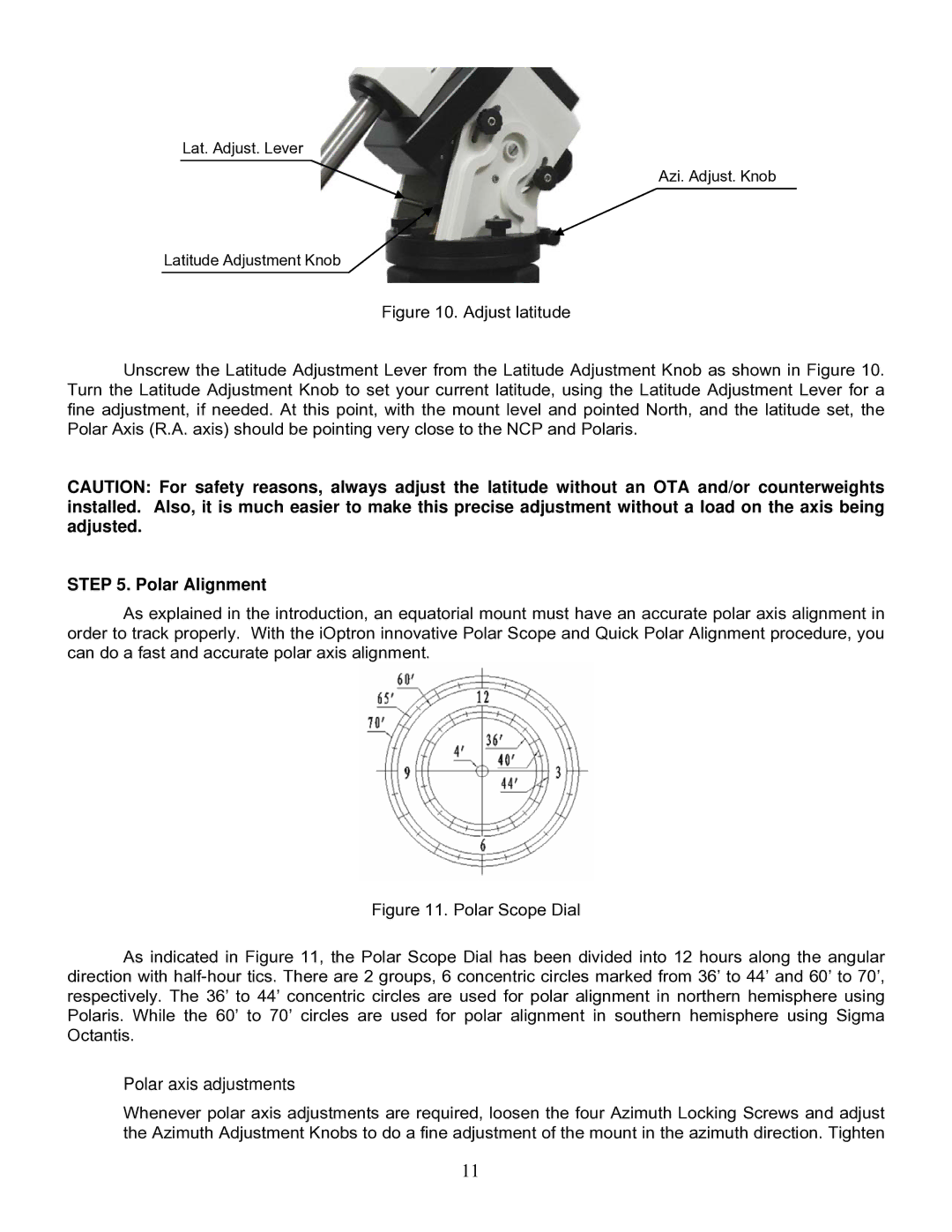
IEQ75-GTTM specifications
The iOptron IEQ75-GT is an advanced equatorial mount designed for amateur astronomers and astrophotographers seeking precision and reliability in their observations. This mount stands out due to its robust construction and innovative technology, making it ideal for a wide range of astronomical applications.One of the main features of the IEQ75-GT is its impressive payload capacity. With the ability to support up to 75 pounds, it can easily accommodate a variety of telescopes and imaging setups, enabling users to explore both deep-sky objects and planetary details. The mount’s solid aluminum construction ensures stability, which is critical for long exposure astrophotography.
The IEQ75-GT is equipped with iOptron's signature GoTo system, allowing for easy navigation across the night sky. With its celestial database that includes over 200,000 objects, users can effortlessly locate and track their desired targets. The advanced GoTo technology also includes a built-in GPS, simplifying the alignment process and providing precise location data for better tracking.
Another notable feature is the mount's dual-axis tracking, which ensures that celestial objects remain in view, even during long exposure imaging sessions. The high-resolution encoders and closed-loop servo motors provide smooth movement and accurate tracking, reducing the risk of star trailing during exposures.
The mount is designed with portability in mind. Its compact size and lightweight construction make it easy to transport, making it a great choice for both backyard observations and remote dark-sky outings. The quick-release system allows for fast setup and teardown, enhancing convenience during stargazing sessions.
iOptron also incorporates unique smart technology in the IEQ75-GT. The mount is compatible with a range of mobile applications, allowing users to control the mount and access additional features directly from their phones or tablets. This level of integration enhances the observing experience and makes it easier to explore the night sky.
Additionally, the IEQ75-GT features a built-in autoguider interface, facilitating long-exposure astrophotography without the need for additional guiding equipment. The mount’s versatility and user-friendly design make it an excellent choice for both novice and experienced astronomers.
In summary, the iOptron IEQ75-GT combines high payload capacity, advanced GoTo technology, sturdy construction, and smart features to deliver a powerful astronomical platform. Whether you're passionate about stargazing or astrophotography, the IEQ75-GT is a worthy investment for any astronomy enthusiast, providing the reliability and precision needed for a successful observing experience.

