English
When connected properly, the top LED on the front of the active speaker should be green. When first plugged in, it will sometimes take several seconds for the Control 2.4G AW active speaker to initialize and “wake up.” Until then, the top LED will be in red. Once the top LED is green, the bottom LED should flash green until the transmitter and active speaker “lock in.” It will then also light in solid green. This LED will light in orange if the local input on the active speaker is selected (see Page 8 under Local Input for more details).
Connection Option B
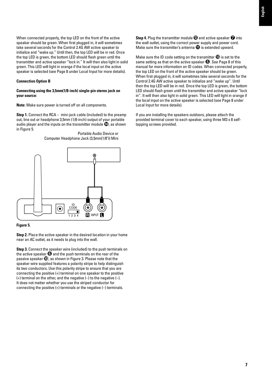
Connecting using the
Note: Make sure power is turned off on all components.
Step 1. Connect the RCA –
Portable Audio Device or Computer Headphone Jack (3,5mm(1/8")) Mini
Step 4. Plug the transmitter module and active speaker into the wall outlet, using the correct power supply and power cord. Make sure the transmitter’s antenna is extended upward.
Make sure the ID code setting on the transmitter is set to the same setting as that on the active speaker . See Page 8 of this manual for more information on ID codes. When connected properly, the top LED on the front of the active speaker should be green. When first plugged in, it will sometimes take several seconds for the Control 2.4G AW active speaker to initialize and “wake up”. Until then the top LED will be in red. Once the top LED is green, the bottom LED should flash green until the transmitter and active speaker “lock in”. It will then also light in solid green. This LED will light in orange if the local input on the active speaker is selected (see Page 8 under Local Input for more details).
If you are installing the speakers outdoors, please attach the provided terminal cover to each speaker, using three M3 x 8 self- tapping screws provided.
ID
CODE
1 2 3 4 R INPUT L
Figure 5.
Step 2. Place the active speaker in the desired location in your home near an AC outlet, as it needs to plug into the wall.
Step 3. Connect the speaker wire (included) to the push terminals on
the active speaker | and the push terminals on the rear of the |
passive speaker | , as shown in Figure 3. Please note that the |
speaker wire supplied features a polarity stripe to help distinguish its two conductors. Use this polarity stripe to ensure that you are connecting the positive (+) terminal on one speaker to the positive
(+)terminal on the other, and the negative
7