MAKING THE CONNECTIONS
A6000GTi SPEAKER
CONNECTIONS
The A6000GTi is a
The A6000GTi can be connected to two independent speaker systems in
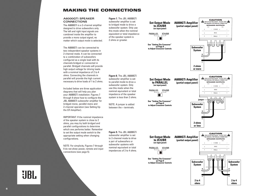
Figure 7. The JBL A6000GTi subwoofer amplifier is set to bridged mode to drive a subwoofer system. Only use this mode when the nominal equivalent or total impedance of the speaker system is
2 ohms or greater.
Figure 8. The JBL A6000GTi subwoofer amplifier is set to parallel mode to drive a
Set Output Mode | A6000GTi Amplifier |
to 2CH/BR | (partial output panel) |
(on input panel) |
|
See “Setting The Crossover”
on Page 8Subwoofer to Adjust Crossover Controls
System
2 ohms or more
Set Output Mode | A6000GTi Amplifier |
to PARALLEL | (partial output panel) |
Included below are three application diagrams that will help you plan your A6000GTi installation. Figures 7 through 9 show how to configure the JBL A6000GTi subwoofer amplifier for
2-channel operation (see Setting Up the GTi Amplifier).
subwoofer system. Only use this mode when the nominal equivalent or total impedance of the speaker system is less than 2 ohms.
NOTE: A jumper is added between the + terminals.
(on input panel)
See “Setting The Crossover” on Page 8
to Adjust Crossover Controls
jumper ![]()
Subwoofer
System
IMPORTANT: If the nominal impedance of the speaker system is close to 2 ohms, you may try both bridged and parallel configurations to determine which one performs better. Remember to set the output mode switch to the appropriate setting when changing configurations.
NOTE: For simplicity, Figures 7 through 9 do not show power, remote and input connections (see page 5).
Figure 9. The JBL A6000GTi subwoofer amplifier is set to 2-channel mode to drive a pair of subwoofers or subwoofer systems with nominal equivalent or total impedances of 2 to 4 ohms.
|
| 2 ohms |
|
| or less |
Set Output Mode | A6000GTi Amplifier | |
to 2CH/BR | (partial output panel) | |
(on input panel) |
|
|
See “Setting The Crossover”
on Page 8
to Adjust Crossover ControlsSubwoofer System
2 to 4 ohms
Subwoofer
System
2 to 4 ohms
6