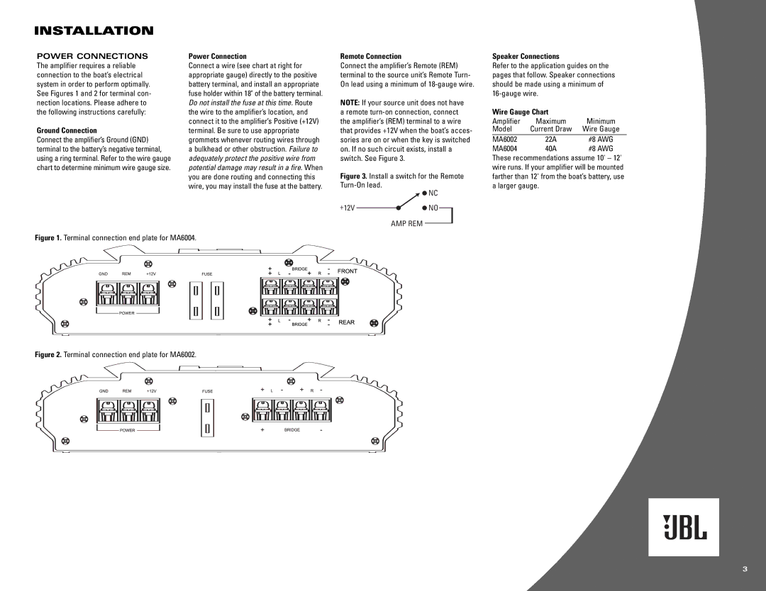
MA6004, MA6002 specifications
The JBL MA6002 and MA6004 are powerful multi-channel amplifiers engineered for optimal performance in 12V audio systems, making them popular choices among car audio enthusiasts. These amplifiers combine advanced technologies with robust construction, delivering a remarkable audio experience tailored for in-vehicle environments.One of the standout features of the JBL MA6002 and MA6004 is their high power output. The MA6002 is a two-channel amplifier that typically delivers 60 watts per channel at 4 ohms, while the MA6004, a four-channel amplifier, can deliver 50 watts per channel at 4 ohms. This impressive output capability ensures that users can enjoy rich, dynamic sound quality at high volumes without distortion.
The MA6002 and MA6004 amplifiers incorporate advanced protection circuitry, which safeguards against overheating, short circuits, and other potential issues. This not only enhances the longevity of the amplifiers but also ensures reliable performance during extended use. Their compact design facilitates seamless installation in a variety of vehicle models, making them suitable for diverse setups.
Both amplifiers utilize high-quality components, including MOSFET power supply and output devices, which contribute to their efficient energy conversion. The use of these components ensures that the amplifiers operate cooler and more effectively, providing better sound quality while consuming less power.
The MA6002 and MA6004 are equipped with comprehensive controls for fine-tuning audio output. Users can adjust gain levels, crossover settings, and bass boost to achieve desired sound characteristics. The built-in low-pass and high-pass filters allow for better integration with subwoofers and other speakers, resulting in a well-rounded audio experience.
Another key characteristic of these JBL amplifiers is their ability to deliver clear sound reproduction at any frequency. Whether it’s deep bass or crisp highs, the MA6002 and MA6004 ensure that every aspect of the audio signal is captured and amplified accurately.
In summary, the JBL MA6002 and MA6004 amplifiers are sophisticated audio components that provide excellent power output, advanced protection features, and customizable controls. Their capacity to deliver rich sound in a compact design makes them a favorite for car audio systems, appealing to both casual listeners and serious audiophiles alike. With these amplifiers, JBL continues to reinforce its reputation as a leader in the audio industry, combining cutting-edge technology with user-centric design.

