Gently pull the slack out of the wire and screw the adapter onto the back of the speaker in two places, as shown.
The floor stand adapter screws may be found in Hardware Bag B. Use the larger screw in the upper screw hole, and the smaller
screw in the lower screw hole.
Screw the floor stand adapter into the floor stand’s threaded insert until the speaker is firmly attached to the stand. Back off slightly from the fully tightened position until the speaker is oriented as desired, then rotate the thumbwheel at
the bottom of the floor stand adapter to secure the speaker to the stand.
Make sure that all four screws are driven into the stud and not into drywall. If the bracket needs to be mounted in drywall, the customer is responsible for selecting and using appropriate wall anchors and screws.
Step 8:
listening position at about
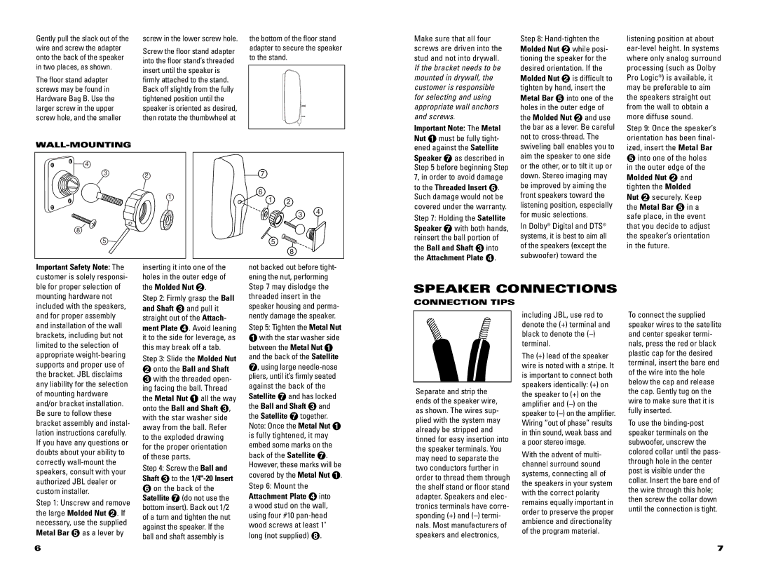
WALL-MOUNTING
4
32
1
8
5
7
6 ![]() 1 2
1 2
3 4
5
8
Important Note: The Metal Nut ¡ must be fully tight- ened against the Satellite Speaker ¶ as described in Step 5 before beginning Step 7, in order to avoid damage to the Threaded Insert §. Such damage would not be covered under the warranty. Step 7: Holding the Satellite Speaker ¶ with both hands, reinsert the ball portion of the Ball and Shaft £ into the Attachment Plate ¢.
the bar as a lever. Be careful not to
In Dolby® Digital and DTS® systems, it is best to aim all of the speakers (except the subwoofer) toward the
Step 9: Once the speaker’s orientation has been final- ized, insert the Metal Bar
∞into one of the holes in the outer edge of the Molded Nut ™ and tighten the Molded Nut ™ securely. Keep the Metal Bar ∞ in a safe place, in the event that you decide to adjust the speaker’s orientation in the future.
Important Safety Note: The customer is solely responsi- ble for proper selection of
inserting it into one of the holes in the outer edge of the Molded Nut ™.
not backed out before tight- ening the nut, performing Step 7 may dislodge the
SPEAKER CONNECTIONS
mounting hardware not included with the speakers, and for proper assembly and installation of the wall brackets, including but not limited to the selection of appropriate
Step 1: Unscrew and remove the large Molded Nut ™. If necessary, use the supplied Metal Bar ∞ as a lever by
Step 2: Firmly grasp the Ball and Shaft £ and pull it straight out of the Attach- ment Plate ¢. Avoid leaning it to the side for leverage, as this may break off a tab. Step 3: Slide the Molded Nut
™onto the Ball and Shaft £ with the threaded open- ing facing the ball. Thread the Metal Nut ¡ all the way onto the Ball and Shaft £, with the star washer side away from the ball. Refer to the exploded drawing for the proper orientation of these parts.
Step 4: Screw the Ball and Shaft £to the 1/4"-20 Insert
§ on the back of the Satellite ¶(do not use the bottom insert). Back out 1/2 of a turn and tighten the nut against the speaker. If the ball and shaft assembly is
threaded insert in the speaker housing and perma- nently damage the speaker. Step 5: Tighten the Metal Nut
¡with the star washer side between the Metal Nut ¡ and the back of the Satellite ¶, using large
a wood stud on the wall, using four #10
CONNECTION TIPS
Separate and strip the ends of the speaker wire, as shown. The wires sup- plied with the system may already be stripped and tinned for easy insertion into the speaker terminals. You may need to separate the two conductors further in order to thread them through the shelf stand or floor stand adapter. Speakers and elec- tronics terminals have corre- sponding (+) and
including JBL, use red to denote the (+) terminal and black to denote the
The (+) lead of the speaker wire is noted with a stripe. It is important to connect both speakers identically: (+) on the speaker to (+) on the amplifier and
With the advent of multi- channel surround sound systems, connecting all of the speakers in your system with the correct polarity remains equally important in order to preserve the proper ambience and directionality of the program material.
To connect the supplied speaker wires to the satellite and center speaker termi- nals, press the red or black plastic cap for the desired terminal, insert the bare end of the wire into the hole below the cap and release the cap. Gently tug on the wire to make sure that it is fully inserted.
To use the
6 | 7 |