Maximum Array Size
There are three variations of the VRX array frame. The
VRX-AF Array Frame
VRX-AF Array Frame
The following table defines the maximum number of speakers that may be suspended using the
the table.
Maximum number of VRX918S in array | 6 | 5 | 4 | 3 | 2 | 1 | 0 |
Maximum number of VRX932LA in array | 0 | 1 | 2 | 3 | 4 | 5 | 6 |
VRX932LA-AF Array Frame
VRX932LA-AF Array Frame
The following table defines the maximum number of speakers that may be suspended using the
Maximum number of VRX918S in array | 4 | 3 | 2 | 1 | 0 |
Maximum number of VRX932LA in array | 1 | 2 | 3 | 4 | 5 |
VRX-SMAF Array Frame
VRX-SMAF Array Frame
The following table defines the maximum number of speakers that may be suspended using the
Maximum number of VRX915S in array | 4 | 3 | 2 | 2 | 2 | 0 |
Maximum number of VRX928LA in array | 0 | 2 | 3 | 4 | 5 | 6 |
The VRX subwoofers must always be on top of the array.
Installing the Array Frame
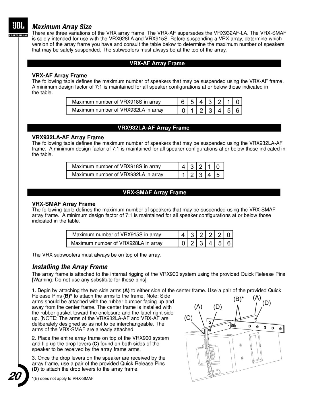
The array frame is attached to the internal rigging of the VRX900 system using the provided Quick Release Pins [Warning: Do not use any substitute for these pins].
1. Begin by attaching the two side arms (A) to either side of the center frame. Use a pair of the provided Quick | ||||
Release Pins (B)* to attach the arms to the frame. Note: Side |
| (B)* | (A) | |
arms should be attached with the rubber bumper facing up and |
| |||
| (D) | |||
|
| |||
away from the center frame. The center frame is installed with | (A) | (D) | ||
| ||||
the rubber gasket toward the enclosure and the label right side |
|
|
| |
up. [NOTE: The arms of the | (C) |
|
| |
deliberately designed so as not to be interchangeable. The arms of the
2.Place the entire array frame on top of the VRX900 system and flip up the drop levers (C) found on both sides of the speaker to be received by the array frame arms.
3. Once the drop levers on the speaker are received by the array frame, use a pair of the provided Quick Release Pins
(D)to attach the drop levers to the array frame.
20 *(B) does not apply to