JL Audio 300/2 owner manual Fuse Requirements TURN-ON Lead Input Section

Models: 300/2

1 11
Download 11 pages 52.44 Kb
Page 4
Image 4

FUSE REQUIREMENTS

TURN-ON LEAD

INPUT SECTION

It is absolutely vital that the main power wire(s)

The 300/2 uses a conventional +12V remote


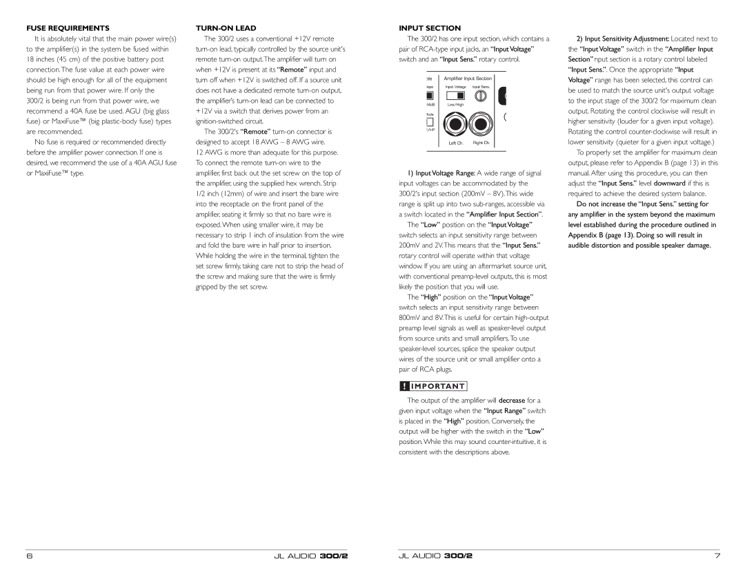
The 300/2 has one input section, which contains a

to the amplifier(s) in the system be fused within

turn-on lead, typically controlled by the source unit's

pair of RCA-type input jacks, an “Input Voltage”

18 inches (45 cm) of the positive battery post

remote turn-on output.The amplifier will turn on

switch and an “Input Sens.” rotary control.

connection.The fuse value at each power wire

when +12V is present at its “Remote” input and


should be high enough for all of the equipment

turn off when +12V is switched off. If a source unit


being run from that power wire. If only the

does not have a dedicated remote turn-on output,


300/2 is being run from that power wire, we

the amplifier’s turn-on lead can be connected to


recommend a 40A fuse be used. AGU (big glass

+12V via a switch that derives power from an


fuse) or MaxiFuse™ (big plastic-body fuse) types

ignition-switched circuit.


are recommended.

The 300/2's “Remote” turn-on connector is


No fuse is required or recommended directly

designed to accept 18 AWG – 8 AWG wire.


before the amplifier power connection. If one is

12 AWG is more than adequate for this purpose.


desired, we recommend the use of a 40A AGU fuse

To connect the remote turn-on wire to the


or MaxiFuse™ type.

amplifier, first back out the set screw on the top of


1) Input Voltage Range: A wide range of signal


the amplifier, using the supplied hex wrench. Strip

input voltages can be accommodated by the


1/2 inch (12mm) of wire and insert the bare wire

300/2's input section (200mV – 8V).This wide


into the receptacle on the front panel of the

range is split up into two sub-ranges, accessible via


amplifier, seating it firmly so that no bare wire is

a switch located in the “Amplifier Input Section”.


exposed. When using smaller wire, it may be


The “Low” position on the “Input Voltage”


necessary to strip 1 inch of insulation from the wire

switch selects an input sensitivity range between


and fold the bare wire in half prior to insertion.

200mV and 2V.This means that the “Input Sens.”


While holding the wire in the terminal, tighten the

rotary control will operate within that voltage


set screw firmly, taking care not to strip the head of

window. If you are using an aftermarket source unit,


the screw and making sure that the wire is firmly

with conventional preamp-level outputs, this is most


gripped by the set screw.

likely the position that you will use.


The “High” position on the “Input Voltage”


switch selects an input sensitivity range between


800mV and 8V.This is useful for certain high-output


preamp level signals as well as speaker-level output


from source units and small amplifiers.To use


speaker-level sources, splice the speaker output


wires of the source unit or small amplifier onto a


pair of RCA plugs.


!

IMPORTANT


The output of the amplifier will decrease for a


given input voltage when the “Input Range” switch


is placed in the “High” position. Conversely, the


output will be higher with the switch in the “Low”


position. While this may sound counter-intuitive, it is


consistent with the descriptions above.

2)Input Sensitivity Adjustment: Located next to the “Input Voltage” switch in the “Amplifier Input Section” nput section is a rotary control labeled

“Input Sens.”. Once the appropriate “Input Voltage” range has been selected, this control can be used to match the source unit's output voltage to the input stage of the 300/2 for maximum clean output. Rotating the control clockwise will result in higher sensitivity (louder for a given input voltage). Rotating the control counter-clockwise will result in lower sensitivity (quieter for a given input voltage.)

To properly set the amplifier for maximum clean output, please refer to Appendix B (page 13) in this manual. After using this procedure, you can then adjust the “Input Sens.” level downward if this is required to achieve the desired system balance.

Do not increase the “Input Sens.” setting for any amplifier in the system beyond the maximum level established during the procedure outlined in Appendix B (page 13). Doing so will result in audible distortion and possible speaker damage.

6

JL AUDIO 300/2

JL AUDIO 300/2

7

Page 4
Image 4
JL Audio 300/2 owner manual Fuse Requirements TURN-ON Lead Input Section

300/2 specifications

The JL Audio 300/2 is a premium two-channel amplifier that stands out in the world of automotive audio for its exceptional sound quality and robust performance. Designed with an emphasis on power and fidelity, this amplifier is ideal for enthusiasts looking to enhance their car audio systems.

One of the standout features of the JL Audio 300/2 is its impressive power output. Capable of delivering 75 watts per channel at 4 ohms and an elevated 150 watts per channel at 2 ohms, this amplifier ensures that your speakers receive the necessary power to produce clear, dynamic sound. This ample power allows for a significant improvement in overall audio performance, making even the most nuanced musical passages come alive.

The amplifier utilizes advanced Class A/B technology, which combines the efficiency of Class B with the linearity of Class A. This results in minimized distortion and improved thermal performance, allowing the JL Audio 300/2 to run cool even under demanding conditions. Such design yields a rich, warm sound, ideal for both casual listeners and serious audiophiles.

The JL Audio 300/2 is also equipped with a fully adjustable crossover system. This system features high-pass and low-pass filters, which enable users to tailor the audio output to their particular speaker configuration. The built-in frequency adjustment allows for precise tuning, optimizing the amplifier's performance in various listening environments.

Durability and design are also key characteristics of the JL Audio 300/2. The amplifier is housed in a sturdy, yet attractive metal chassis designed to withstand the rigors of automotive use. Its sleek aesthetic and compact design make installation straightforward, fitting seamlessly into a variety of automotive environments.

Moreover, the amplifier features a secure input terminal and robust speaker outputs that allow for reliable connections, reducing the chances of interference or loss of signal quality.

In summary, the JL Audio 300/2 is a high-performance two-channel amplifier that marries powerful output with advanced audio technology. Its Class A/B design, customizable crossover options, and durable construction make it a perfect choice for car audio enthusiasts seeking to elevate their listening experience. Whether powering high-quality component speakers or adding depth to an audio system, the JL Audio 300/2 is engineered to deliver impressive sound fidelity and reliability.