remote control
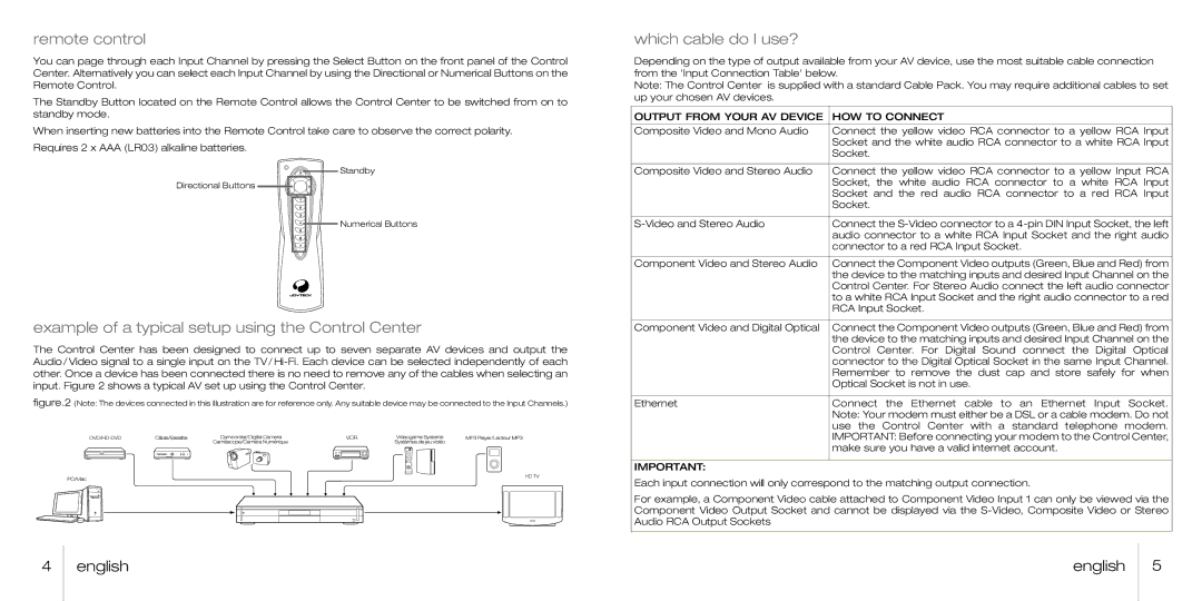
You can page through each Input Channel by pressing the Select Button on the front panel of the Control Center. Alternatively you can select each Input Channel by using the Directional or Numerical Buttons on the Remote Control.
The Standby Button located on the Remote Control allows the Control Center to be switched from on to standby mode.
When inserting new batteries into the Remote Control take care to observe the correct polarity. Requires 2 x AAA (LR03) alkaline batteries.
Standby
Directional Buttons ![]()
![]()
![]()
Numerical Buttons
example of a typical setup using the Control Center
The Control Center has been designed to connect up to seven separate AV devices and output the Audio/Video signal to a single input on the
figure.2 (Note: The devices connected in this illustration are for reference only. Any suitable device may be connected to the Input Channels.)
which cable do I use?
Depending on the type of output available from your AV device, use the most suitable cable connection from the 'Input Connection Table' below.
Note: The Control Center is supplied with a standard Cable Pack. You may require additional cables to set up your chosen AV devices.
OUTPUT FROM YOUR AV DEVICE | HOW TO CONNECT |
Composite Video and Mono Audio | Connect the yellow video RCA connector to a yellow RCA Input |
| Socket and the white audio RCA connector to a white RCA Input |
| Socket. |
|
|
Composite Video and Stereo Audio | Connect the yellow video RCA connector to a yellow Input RCA |
| Socket, the white audio RCA connector to a white RCA Input |
| Socket and the red audio RCA connector to a red RCA Input |
| Socket. |
|
|
Connect the | |
| audio connector to a white RCA Input Socket and the right audio |
| connector to a red RCA Input Socket. |
|
|
Component Video and Stereo Audio | Connect the Component Video outputs (Green, Blue and Red) from |
| the device to the matching inputs and desired Input Channel on the |
| Control Center. For Stereo Audio connect the left audio connector |
| to a white RCA Input Socket and the right audio connector to a red |
| RCA Input Socket. |
|
|
Component Video and Digital Optical | Connect the Component Video outputs (Green, Blue and Red) from |
| the device to the matching inputs and desired Input Channel on the |
| Control Center. For Digital Sound connect the Digital Optical |
| connector to the Digital Optical Socket in the same Input Channel. |
| Remember to remove the dust cap and store safely for when |
| Optical Socket is not in use. |
|
|
Ethernet | Connect the Ethernet cable to an Ethernet Input Socket. |
| Note: Your modem must either be a DSL or a cable modem. Do not |
| use the Control Center with a standard telephone modem. |
| IMPORTANT: Before connecting your modem to the Control Center, |
| make sure you have a valid internet account. |
|
|
IMPORTANT:
Each input connection will only correspond to the matching output connection.
For example, a Component Video cable attached to Component Video Input 1 can only be viewed via the Component Video Output Socket and cannot be displayed via the
4 | english | english | 5 |
|
|
|
|