6 Connections
Cable and VCR Connections
There are three basic types of antenna or cable connections:
•If you have an antenna or have a cable system that does not require you use a cable box to select channels, please refer to Diagram #1.
•If you have a cable system that requires the use of a cable box to access all the channels, please refer to Diagram #2.
•If you have a cable system that requires the use of a cable box to access certain premium channels, but not “basic” cable channels, please refer to Diagram #3.
•For instructions on connecting a VCR only, please see the Quick Setup Guide.
•For information on using Picture In Picture (PIP), please see page 28.
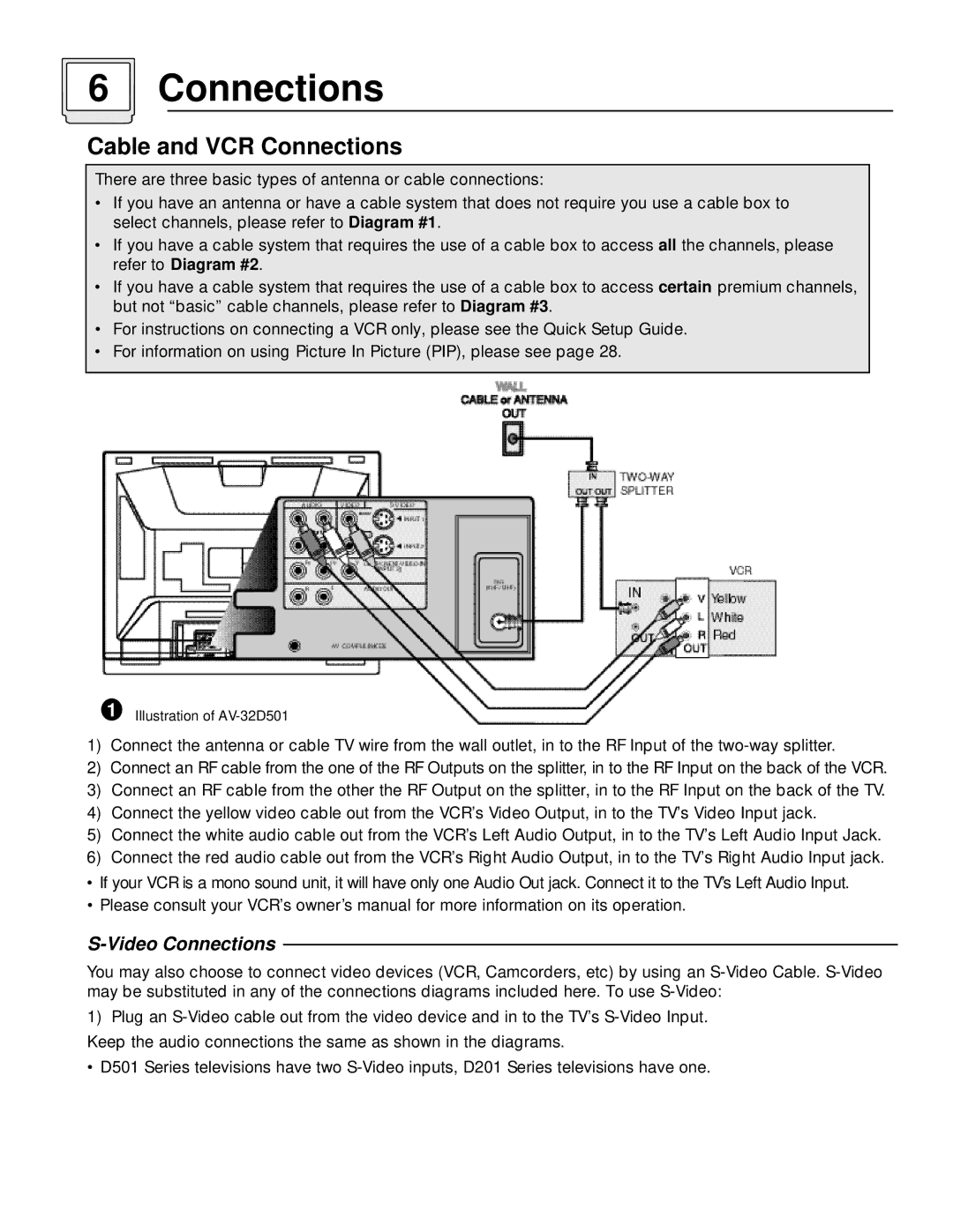
1Illustration of
1)Connect the antenna or cable TV wire from the wall outlet, in to the RF Input of the
2)Connect an RF cable from the one of the RF Outputs on the splitter, in to the RF Input on the back of the VCR.
3)Connect an RF cable from the other the RF Output on the splitter, in to the RF Input on the back of the TV.
4)Connect the yellow video cable out from the VCR’s Video Output, in to the TV’s Video Input jack.
5)Connect the white audio cable out from the VCR’s Left Audio Output, in to the TV’s Left Audio Input Jack.
6)Connect the red audio cable out from the VCR’s Right Audio Output, in to the TV’s Right Audio Input jack.
•If your VCR is a mono sound unit, it will have only one Audio Out jack. Connect it to the TV’s Left Audio Input.
•Please consult your VCR’s owner’s manual for more information on its operation.
S-Video Connections
You may also choose to connect video devices (VCR, Camcorders, etc) by using an
1)Plug an
•D501 Series televisions have two