CONNECTION TO OTHER EQUIPMENT
The exact arrangement you use to interconnect various video and audio components to the TV is dependent on the model and features of each component. Check the User’s Guide provided with each component for the location of video and audio inputs and outputs.
The connection diagrams in the following are offered as suggestions. You may need to modify them to accommodate your particular assortment of components. The diagrams are intended to show component video and audio interconnections only.
Press the INPUT button to select the AV mode to use the TV as a monitor.
Operate your VCR as usual.
TV/AV SELECTION
If you connect the TV to VCR, camcorder, TV game or DVD you can select by pressing the INPUT button.
Press the INPUT button repeatedly to select the desired mode.
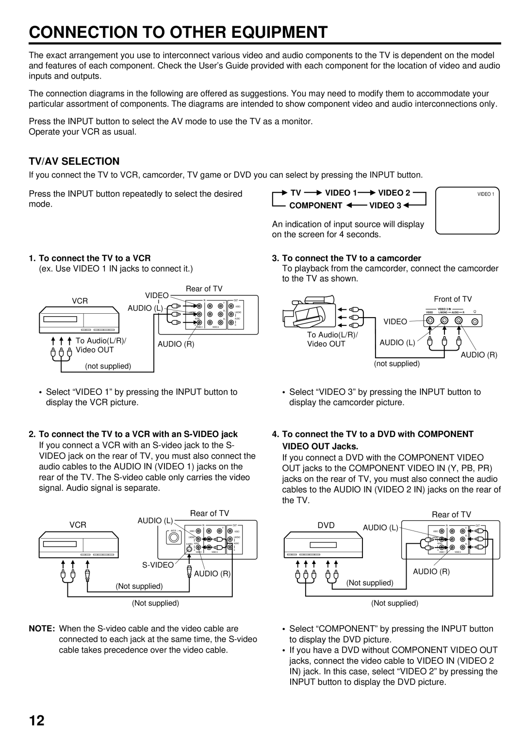
1.To connect the TV to a VCR
(ex. Use VIDEO 1 IN jacks to connect it.)
| VIDEO | Rear of TV |
| ||
VCR | IN | Y | OUT | ||
AUDIO (L) | |||||
| VIDEO | PB | VIDEO | ||
|
| L/MONO |
| L/MONO | |
|
| AUDIO | PR | AUDIO | |
|
| R | VIDEO 2 | R | |
|
| VIDEO 1 |
| ||
To Audio(L/R)/ | AUDIO (R) | |
Video OUT | ||
| ||
(not supplied) |
|
TV |
| VIDEO 1 |
| VIDEO 2 |
| VIDEO 1 |
|
|
|
COMPONENT ![]() VIDEO 3
VIDEO 3 ![]()
An indication of input source will display on the screen for 4 seconds.
3.To connect the TV to a camcorder
To playback from the camcorder, connect the camcorder to the TV as shown.
| Front of TV |
| VIDEO 3 IN |
| VIDEO L/MONO AUDIO R |
| VIDEO |
To Audio(L/R)/ | AUDIO (L) |
Video OUT | |
| AUDIO (R) |
| (not supplied) |
•Select “VIDEO 1” by pressing the INPUT button to display the VCR picture.
2.To connect the TV to a VCR with an
| AUDIO (L) | Rear of TV | |
VCR | IN | Y | |
|
| OUT | |
| ANT(75Ω ) | VIDEO | VIDEO |
|
| L/MONO | L/MONO |
|
| AUDIO | |
|
| R | R |
|
| VIDEO 1 | VIDEO 2 |
![]()
![]()
![]()
![]() AUDIO (R)
AUDIO (R)
(Not supplied) (Not supplied)
•Select “VIDEO 3” by pressing the INPUT button to display the camcorder picture.
4.To connect the TV to a DVD with COMPONENT VIDEO OUT Jacks.
If you connect a DVD with the COMPONENT VIDEO OUT jacks to the COMPONENT VIDEO IN (Y, PB, PR) jacks on the rear of TV, you must also connect the audio cables to the AUDIO IN (VIDEO 2 IN) jacks on the rear of the TV.
Rear of TV
DVD | AUDIO (L) | IN | OUT |
| Y | ||
| VIDEO |
| |
|
| L/MONO | PB |
|
|
| |
|
| AUDIO | PR |
|
| R | VIDEO 2 |
|
| VIDEO 1 | |
|
| AUDIO (R) |
|
| (Not supplied) |
|
|
(Not supplied)
NOTE: When the
•Select “COMPONENT” by pressing the INPUT button to display the DVD picture.
•If you have a DVD without COMPONENT VIDEO OUT jacks, connect the video cable to VIDEO IN (VIDEO 2 IN) jack. In this case, select “VIDEO 2” by pressing the INPUT button to display the DVD picture.
12