KS-AR8001D specifications
The JVC KS-AR8001D is a part of JVC’s acclaimed lineup of car amplifiers, designed to enhance the audio experience for car enthusiasts and everyday users alike. This powerful amplifier delivers an exceptional audio output, making it a popular choice for those looking to boost their vehicle's sound system.One of the primary features of the KS-AR8001D is its impressive rated power output. With a robust 800 watts RMS power rating at 1 ohm, it offers excellent sound clarity and stability even at high volumes. This feature ensures a dynamic listening experience, as it can handle low-frequency bass notes with ease, making it suitable for various musical genres, especially for bass-heavy tracks.
In terms of technology, the KS-AR8001D incorporates a high-efficiency Class D design. This means it generates less heat and can deliver more power while consuming less energy compared to traditional Class AB amplifiers. The compact footprint of the Class D design also allows for flexible installation in limited spaces, a common concern in many vehicles.
Another noteworthy characteristic of the KS-AR8001D is its extensive protection circuitry. The amplifier is equipped with features that safeguard against overheating, short-circuits, and overcurrent situations. This durability ensures the longevity of the unit, even during prolonged usage or under demanding conditions.
The amplifier also includes adjustable gain control, a low-pass filter, and a bass boost feature, enabling users to customize their sound to fit personal preferences. The low-pass filter allows precise tuning of the frequency range, ensuring that only the desired frequencies are sent to the subwoofer. Meanwhile, the bass boost feature enhances lower frequencies, providing an extra punch to the bass, ideal for those who crave powerful low-end sounds.
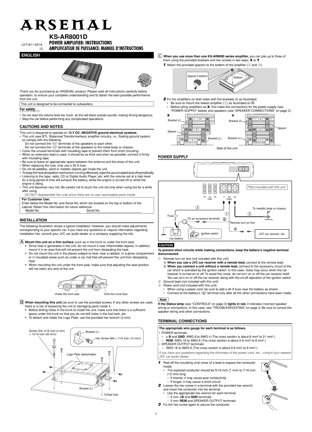
Furthermore, the amplifier’s sleek design, complete with a rugged casing, ensures it can withstand the rigors of vehicle environments. Its aesthetic appeal also adds a modern touch to any audio setup.
In conclusion, the JVC KS-AR8001D stands out in the market for its powerful output, advanced Class D technology, comprehensive protection features, and user-friendly adjustments. Whether you are an audiophile or simply looking to enhance your in-car listening experience, the KS-AR8001D offers a compelling combination of performance and reliability.