G
IRIS
VIDEO |
|
DC |
|
L | H |
LEVEL
LEVEL
L H | LEVEL |
|
AvPk | ALC | BF LOCK |
ALC
H
4 ![]()
![]()
![]() 1,5
1,5
I | 8 |
| 7 |
| 6 |
| 5 |
| 4 |
| 3 |
| 2 |
1
J [: mm]
123 | |
50 | 115 |
|
50 | 58 |
32.5
42
30
| ® |
|
|
| Printed in Thailand |
|
| |
VICTOR COMPANY OF JAPAN, LIMITED | ©2002 VICTOR COMPANY OF JAPAN, LIMITED | |
® | is a Registered Trademark owned by VICTOR COMPANY OF JAPAN, LTD. | |
| ||
® | is a Registrated Trademark in Japan,the U.S.A., the U.K. and many other countries. | |
| ||
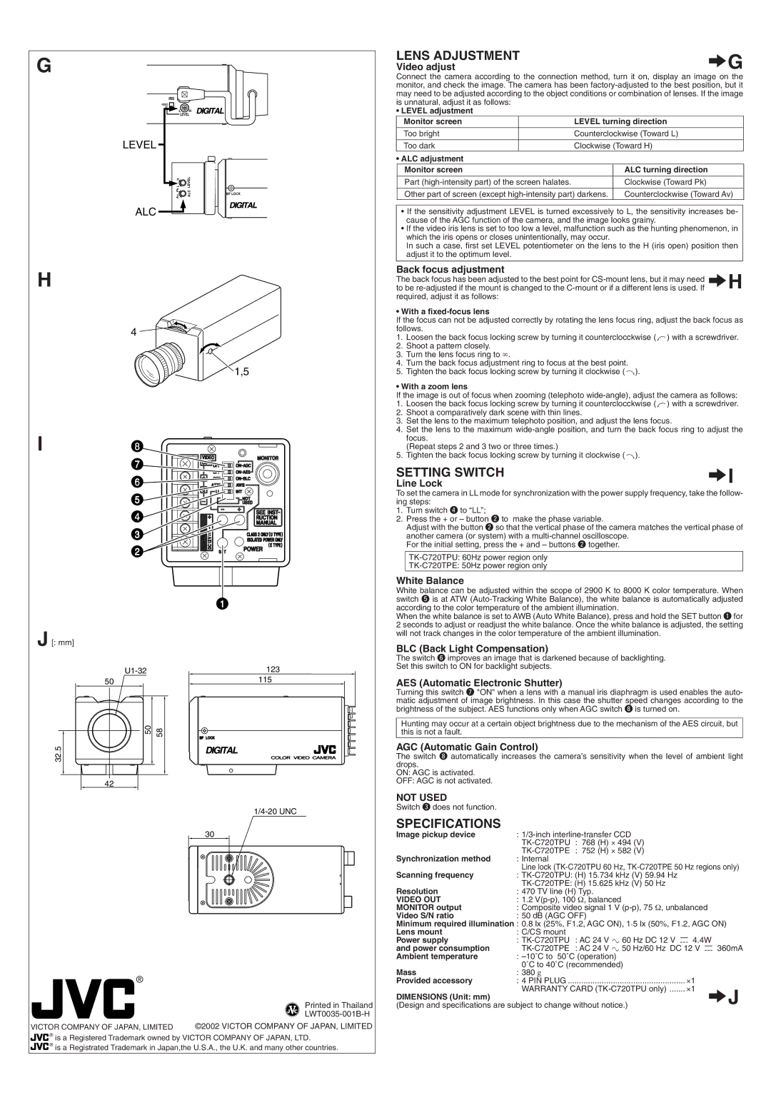
LENS ADJUSTMENT | ∆G | |
Video adjust | ||
| ||
Connect the camera according to the connection method, turn it on, display an image on the | ||
monitor, and check the image. The camera has been | ||
may need to be adjusted according to the object conditions or combination of lenses. If the image | ||
is unnatural, adjust it as follows: |
|
• LEVEL adjustment |
|
Monitor screen | LEVEL turning direction |
Too bright | Counterclockwise (Toward L) |
Too dark | Clockwise (Toward H) |
• ALC adjustment |
|
Monitor screen | ALC turning direction |
Part | Clockwise (Toward Pk) |
Other part of screen (except | Counterclockwise (Toward Av) |
|
|
•If the sensitivity adjustment LEVEL is turned excessively to L, the sensitivity increases be- cause of the AGC function of the camera, and the image looks grainy.
•If the video iris lens is set to too low a level, malfunction such as the hunting phenomenon, in which the iris opens or closes unintentionally, may occur.
In such a case, first set LEVEL potentiometer on the lens to the H (iris open) position then adjust it to the optimum level.
Back focus adjustment | ∆H |
The back focus has been adjusted to the best point for | |
to be |
|
required, adjust it as follows: |
|
• With a |
|
If the focus can not be adjusted correctly by rotating the lens focus ring, adjust the back focus as | |
follows. |
|
1.Loosen the back focus locking screw by turning it counterclocckwise ( ![]() ) with a screwdriver.
) with a screwdriver.
2.Shoot a pattern closely.
3.Turn the lens focus ring to ∞.
4.Turn the back focus adjustment ring to focus at the best point.
5.Tighten the back focus locking screw by turning it clockwise ( ![]() ).
).
• With a zoom lens If the image is out of focus when zooming (telephoto
1.Loosen the back focus locking screw by turning it counterclocckwise ( ![]() ) with a screwdriver.
) with a screwdriver.
2.Shoot a comparatively dark scene with thin lines.
3.Set the lens to the maximum telephoto position, and adjust the lens focus.
4.Set the lens to the maximum
(Repeat steps 2 and 3 two or three times.)
5.Tighten the back focus locking screw by turning it clockwise ( ![]() ).
).
SETTING SWITCH | ∆I |
Line Lock |
|
To set the camera in LL mode for synchronization with the power supply frequency, take the follow- | |
ing steps: |
|
1.Turn switch r to “LL”;
2.Press the + or – button w to make the phase variable.
Adjust with the button w so that the vertical phase of the camera matches the vertical phase of
another camera (or system) with a
White Balance |
|
|
|
|
|
|
|
White balance can be adjusted within the scope of 2900 K to 8000 K color temperature. When | |||||||
switch t is at ATW | |||||||
according to the color temperature of the ambient illumination. |
|
|
|
| |||
When the white balance is set to AWB (Auto White Balance), press and hold the SET button q for | |||||||
2 seconds to adjust or readjust the white balance. Once the white balance is adjusted, the setting | |||||||
will not track changes in the color temperature of the ambient illumination. |
|
|
|
| |||
BLC (Back Light Compensation) |
|
|
|
|
|
| |
The switch y improves an image that is darkened because of backlighting. |
|
|
|
| |||
Set this switch to ON for backlight subjects. |
|
|
|
|
|
| |
AES (Automatic Electronic Shutter) |
|
|
|
|
|
| |
Turning this switch u "ON" when a lens with a manual iris diaphragm is used enables the auto- | |||||||
matic adjustment of image brightness. In this case the shutter speed changes according to the | |||||||
brightness of the subject. AES functions only when AGC switch i is turned on. |
|
|
|
| |||
Hunting may occur at a certain object brightness due to the mechanism of the AES circuit, but | |||||||
this is not a fault. |
|
|
|
|
|
|
|
AGC (Automatic Gain Control) |
|
|
|
|
|
| |
The switch i automatically increases the camera’s sensitivity when the level of ambient light | |||||||
drops. |
|
|
|
|
|
|
|
ON: AGC is activated. |
|
|
|
|
|
|
|
OFF: AGC is not activated. |
|
|
|
|
|
|
|
NOT USED |
|
|
|
|
|
|
|
Switch e does not function. |
|
|
|
|
|
|
|
SPECIFICATIONS |
|
|
|
|
|
|
|
Image pickup device | : |
|
|
|
| ||
|
| : | 768 (H) ⋅ 494 (V) |
|
|
|
|
Synchronization method |
| : | 752 (H) ⋅ 582 (V) |
|
|
|
|
: Internal |
|
|
|
|
|
| |
Scanning frequency | Line lock | ||||||
: |
|
|
|
| |||
Resolution |
|
|
|
| |||
: 470 TV line (H) Typ. |
|
|
|
| |||
VIDEO OUT | : 1.2 |
|
|
|
| ||
MONITOR output | : Composite video signal 1 V |
| |||||
Video S/N ratio | : 50 dB (AGC OFF) |
|
|
|
| ||
|
|
| . |
|
|
|
|
Minimum required illumination : 0.8 lx (25%, F1.2, AGC ON), 1 5 lx (50%, F1.2, AGC ON) | |||||||
Lens mount | : C/CS mount |
|
|
|
|
|
|
Power supply | : | : AC 24 V ` 60 Hz DC 12 V |
| 4.4W |
| ||
|
| ||||||
and power consumption |
| : AC 24 V ` 50 Hz/60 Hz DC 12 V |
| 360mA | |||
| |||||||
Ambient temperature | : |
|
|
|
| ||
Mass | 0˚C to 40˚C (recommended) |
|
|
|
| ||
: 380 g |
|
|
|
|
|
| |
Provided accessory | : 4 PIN PLUG .................................................... ⋅1 |
|
| ||||
DIMENSIONS (Unit: mm) | WARRANTY CARD | ∆J | |||||
|
|
|
|
| |||
(Design and specifications are subject to change without notice.) |
|
|
|
| |||