Rear
< Rear Panel >
24
1
2
1
2
AC IN
DC IN
12V
+
-
25
| SET UP | |
| VIDEO A | |
| IN | OUT |
CUT OFF |
|
|
B |
|
|
| VIDEO B | |
R | IN | OUT |
|
| |
G |
|
|
DRIVE | IN |
|
|
| |
R | Y/C |
|
| OUT |
|
G | EXT SYNC | |
| ||
| IN | OUT |
| AUDIO |
|
| IN | OUT |
| A |
|
|
| B |
|
| NORMAL |
|
| AFC |
|
| FAST |
TALLY/
REMOTE
VIDEO A |
|
| |
IN | OUT |
| 15 |
|
|
| |
VIDEO B |
|
| |
IN | OUT |
|
|
|
|
| 16 |
IN |
|
|
|
Y/C |
|
|
|
OUT |
|
|
|
EXT SYNC |
|
| |
IN | OUT |
| 17 |
|
|
| |
AUDIO |
|
|
|
IN | OUT |
|
|
A |
|
| 18 |
|
| B | 19 |
|
|
| |
| NORMAL |
| 20 |
| AFC |
| |
|
|
| |
| FAST |
|
|
22
To AC outlet
(120 V AC, 50/60 Hz)
23
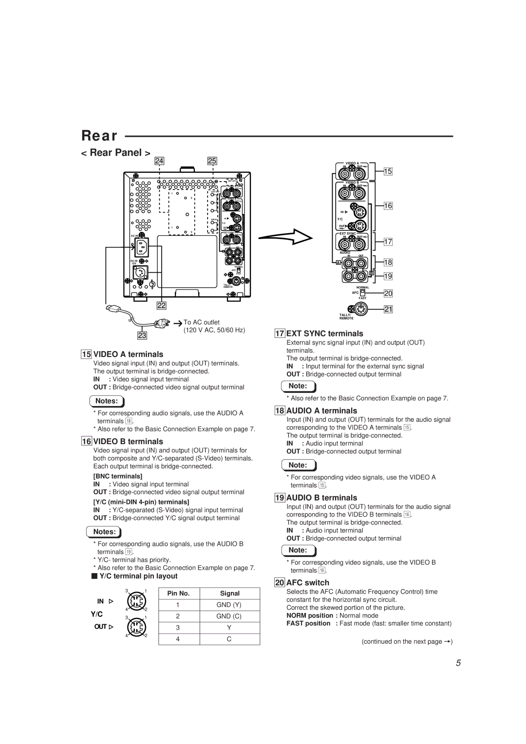
15 VIDEO A terminals
Video signal input (IN) and output (OUT) terminals. The output terminal is
IN : Video signal input terminal
OUT :
Notes:
*For corresponding audio signals, use the AUDIO A terminals *.
*Also refer to the Basic Connection Example on page 7.
16 VIDEO B terminals
Video signal input (IN) and output (OUT) terminals for both composite and
[BNC terminals]
IN : Video signal input terminal
OUT :
[Y/C (mini-DIN 4-pin) terminals]
IN :
OUT :
Notes:
*For corresponding audio signals, use the AUDIO B terminals (.
*Y/C- terminal has priority.
*Also refer to the Basic Connection Example on page 7.
Y/C terminal pin layout
3 | 1 | Pin No. | Signal |
|
|
IN |
|
| 1 | GND (Y) |
| 4 | 2 | ||
Y/C |
|
| ||
3 | 1 | 2 | GND (C) | |
OUT |
|
| 3 | Y |
| 4 | 2 | 4 | C |
|
|
|
21
TALLY/
REMOTE
17 EXT SYNC terminals
External sync signal input (IN) and output (OUT) terminals.
The output terminal is
IN : Input terminal for the external sync signal
OUT :
Note:
* Also refer to the Basic Connection Example on page 7.
18 AUDIO A terminals
Input (IN) and output (OUT) terminals for the audio signal corresponding to the VIDEO A terminals %.
The output terminal is
OUT :
Note:
*For corresponding video signals, use the VIDEO A terminals %.
19 AUDIO B terminals
Input (IN) and output (OUT) terminals for the audio signal corresponding to the VIDEO B terminals ^.
The output terminal is
OUT :
Note:
*For corresponding video signals, use the VIDEO B terminals ^.
20 AFC switch
Selects the AFC (Automatic Frequency Control) time constant for the horizontal sync circuit.
Correct the skewed portion of the picture. NORM position : Normal mode
FAST position : Fast mode (fast: smaller time constant)
(continued on the next page =)
5
