
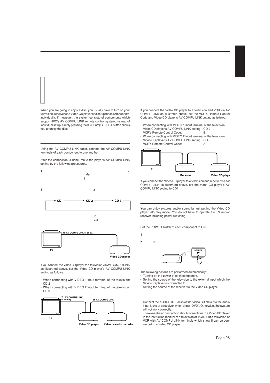
XL-MV7000GD specifications
The JVC XL-MV7000GD is a distinguished model in the realm of high-fidelity audio players, crafted to meet the needs of audiophiles and casual listeners alike. Known for its blend of advanced technology and user-friendly features, this device has made a significant mark in the audio equipment landscape.With a sleek and stylish design, the XL-MV7000GD catches the eye while complementing any modern audio setup. It is primarily recognized for its robust CD player capabilities, which deliver outstanding sound quality through precision engineering. Utilizing a high-performance digital-to-analog converter (DAC), this player ensures that audio playback is both clear and dynamic, capturing the nuances of every musical note.
One of the standout features of the XL-MV7000GD is its integrated MP3 playback capability. This allows users to enjoy compressed audio formats without sacrificing sound quality, making it a versatile choice for those who have a vast digital music library. The device supports a wide array of file formats, including CD-DA, CD-R/RW, and MP3, making it adaptable for various audio sources.
The XL-MV7000GD comes equipped with an advanced anti-vibration system, which significantly minimizes unwanted sound distortions caused by physical movement. This technology is paramount for maintaining sound integrity, especially during high-volume playback or when the device is in motion. Additionally, it features a robust motor mechanism that ensures precise tracking of the audio disc and minimizes reading errors.
Connectivity options are another highlight of the JVC XL-MV7000GD. It includes both digital and analog outputs, allowing it to connect seamlessly with external amplifiers and speaker systems. This flexibility provides users with options to customize their sound experience according to their preferences and the specifics of their audio environment.
Furthermore, the device carries a user-friendly interface, featuring an intuitive remote control that simplifies navigation through tracks and settings. An easy-to-read display provides essential information about the currently playing track, making it easy for users to skip songs or adjust volumes on the fly.
In summary, the JVC XL-MV7000GD stands out with its combination of high-fidelity sound quality, versatile playback capabilities, effective anti-vibration technology, and user-friendly design. For anyone serious about their audio experience, this model represents a solid investment, delivering both performance and convenience in one elegant package.