FUNCTIONAL DESCRIPTION
6
2
1
3
8![]()
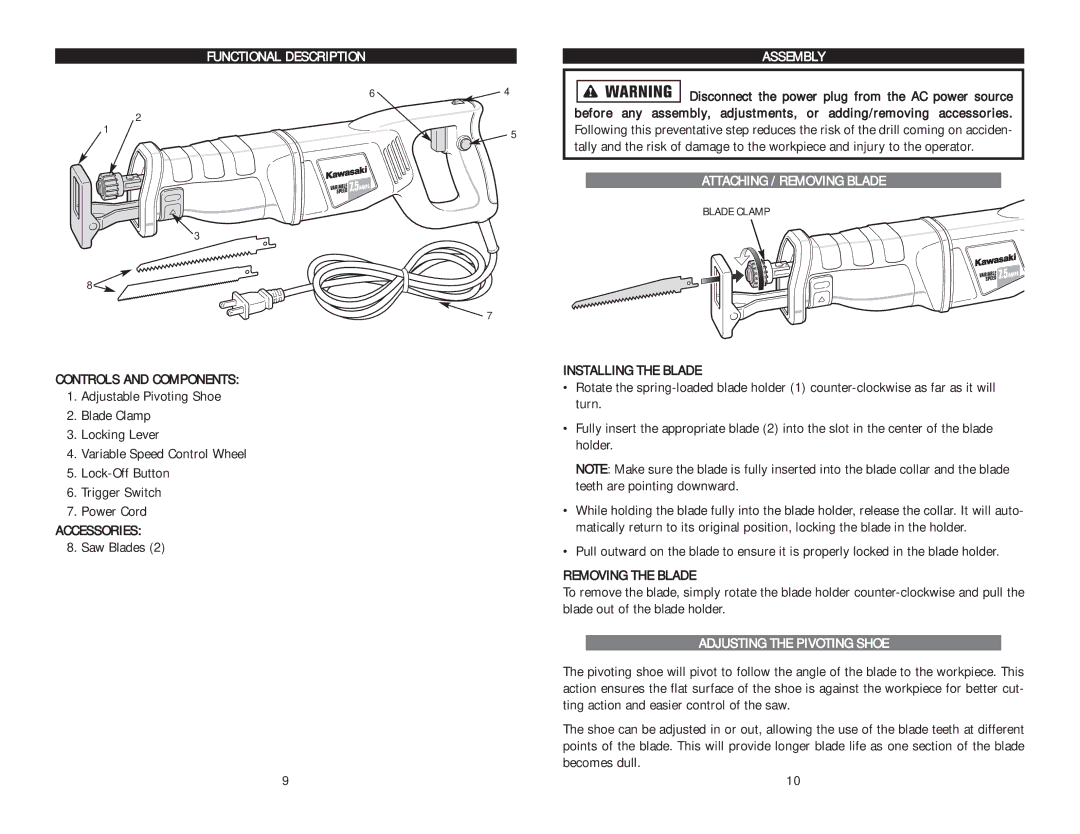
CONTROLS AND COMPONENTS:
1.Adjustable Pivoting Shoe
2.Blade Clamp
3.Locking Lever
4.Variable Speed Control Wheel
5.
6.Trigger Switch
7.Power Cord
ACCESSORIES:
8. Saw Blades (2)
4
5
![]() 7
7
ASSEMBLY
![]()
![]()
![]()
![]()
![]()
![]()
![]() Disconnect the power plug from the AC power source before any assembly, adjustments, or adding/removing accessories. Following this preventative step reduces the risk of the drill coming on acciden- tally and the risk of damage to the workpiece and injury to the operator.
Disconnect the power plug from the AC power source before any assembly, adjustments, or adding/removing accessories. Following this preventative step reduces the risk of the drill coming on acciden- tally and the risk of damage to the workpiece and injury to the operator.
ATTACHING / REMOVING BLADE
BLADE CLAMP
INSTALLING THE BLADE
•Rotate the
•Fully insert the appropriate blade (2) into the slot in the center of the blade holder.
NOTE: Make sure the blade is fully inserted into the blade collar and the blade teeth are pointing downward.
•While holding the blade fully into the blade holder, release the collar. It will auto- matically return to its original position, locking the blade in the holder.
•Pull outward on the blade to ensure it is properly locked in the blade holder.
REMOVING THE BLADE
To remove the blade, simply rotate the blade holder
ADJUSTING THE PIVOTING SHOE
The pivoting shoe will pivot to follow the angle of the blade to the workpiece. This action ensures the flat surface of the shoe is against the workpiece for better cut- ting action and easier control of the saw.
The shoe can be adjusted in or out, allowing the use of the blade teeth at different points of the blade. This will provide longer blade life as one section of the blade becomes dull.
9 | 10 |