This water heater shall not be connected to any heating systems or component(s) used with a
All piping components connected to this unit for space heating applications shall be suitable for use with potable water.
Toxic chemicals, such as those used for boiler treatment shall not be introduced into this system.
Water supply systems may, because of such events as high line pressure, frequent
The water within the water heater tank expands as it is heated and increases the pressure of the water system. If the relieving point of the water heater’s
NOTE: To protect against untimely corrosion of hot and cold water fittings, it is strongly recommended that
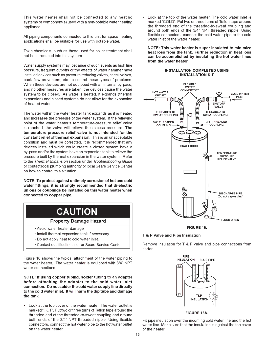
Figure 16 shows the typical attachment of the water piping to the water heater. The water heater is equipped with 3/4” NPT water connections.
NOTE: If using copper tubing, solder tubing to an adapter before attaching the adapter to the cold water inlet connection. Do not solder the cold water supply line directly to the cold water inlet. It will harm the dip tube and damage the tank.
•Look at the top cover of the water heater. The water outlet is marked “HOT”. Put two or three turns of Teflon tape around the threaded end of the threaded-to-sweat coupling and around both ends of the 3/4” NPT threaded nipple. Using flexible connectors, connect the hot water pipe to the hot water outlet on the water heater.
•Look at the top of the water heater. The cold water inlet is marked “COLD”. Put two or three turns of Teflon tape around the threaded end of the threaded-to-sweat coupling and around both ends of the 3/4” NPT threaded nipple. Using flexible connectors, connect the cold water pipe to the cold water inlet of the water heater.
NOTE: This water heater is super insulated to minimize heat loss from the tank. Further reduction in heat loss can be accomplished by insulating the hot water lines from the water heater.
INSTALLATION COMPLETED USING
INSTALLATION KIT
FIGURE 16.
T & P Valve and Pipe Insulation
Remove insulation for T & P valve and pipe connections from
carton.
FIGURE 16A.
Fit pipe insulation over the incoming cold water line and the hot water line. Make sure that the insulation is against the top cover of the heater.
13