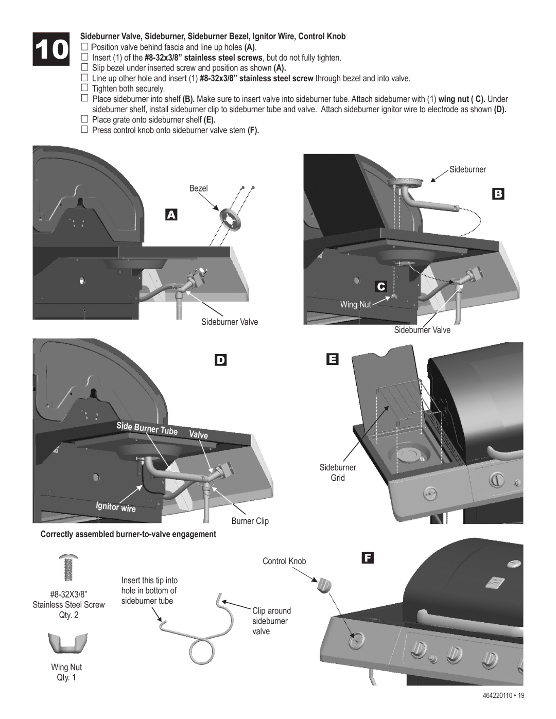
Sideburner Valve, Sideburner, Sideburner Bezel, Ignitor Wire, Control Knob
10![]() Position valve behind fascia and line up holes (A).
Position valve behind fascia and line up holes (A).
![]() Insert (1) of the
Insert (1) of the
![]() Slip bezel under inserted screw and position as shown (A).
Slip bezel under inserted screw and position as shown (A).
![]() Line up other hole and insert (1)
Line up other hole and insert (1)
![]() Tighten both securely.
Tighten both securely.
![]() Place sideburner into shelf (B). Make sure to insert valve into sideburner tube. Attach sideburner with (1) wing nut ( C). Under
Place sideburner into shelf (B). Make sure to insert valve into sideburner tube. Attach sideburner with (1) wing nut ( C). Under
sideburner shelf, install sideburner clip to sideburner tube and valve. Attach sideburner ignitor wire to electrode as shown (D). ![]() Place grate onto sideburner shelf (E).
Place grate onto sideburner shelf (E).
![]() Press control knob onto sideburner valve stem (F).
Press control knob onto sideburner valve stem (F).
Sideburner
Bezel
B
A
C
Wing Nut ![]()
Sideburner Valve
Sideburner Valve
D | E |
Side |
|
Burner |
|
Tube | Valve |
|
Sideburner
Grid
Ignitor wire
|
| Burner Clip |
Correctly assembled |
| |
|
| Control Knob |
| Insert this tip into |
|
hole in bottom of |
| |
sideburner tube |
| |
Stainless Steel Screw | Clip around | |
Qty. 2 |
| |
| sideburner | |
|
| |
|
| valve |
Wing Nut |
|
|
Qty. 1 |
|
|
F
464220110 • 19