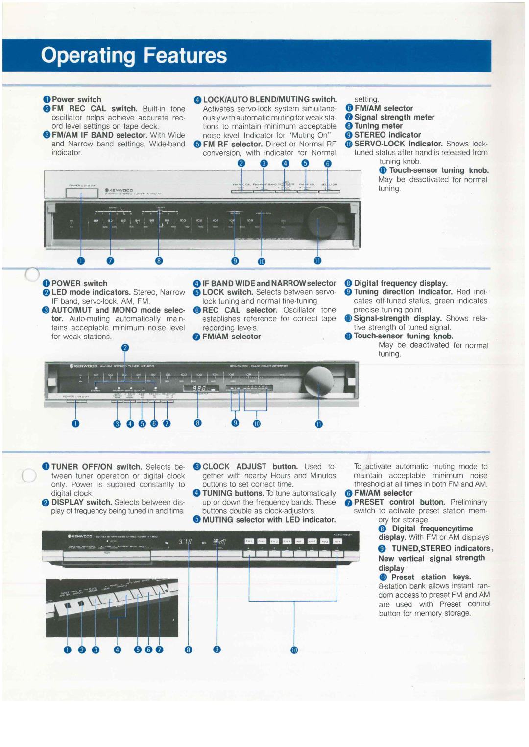
O Power switch
©FM REC CAL switch.
©FM/AM IF BAND selector. With Wide and Narrow band settings.
© POWER switch
©LED mode indicators. Stereo, Narrow IF band,
©AUTO/MUT and MONO mode selec- tor.
©TUNER OFF/ON switch. Selects be tween tuner operation or digital clock only. Power is supplied constantly to digital clock.
© DISPLAY switch. Selects between dis- play of frequency being tuned in and time.
O LOCK/AUTO BLEND/MUTING switch. Activates
©FM RF selector. Direct or Normal RF conversion, with indicator for Normal
© IF BAND WIDE and NARROW selector © LOCK switch. Selects between servo-
lock tuning and normal
establishes reference for correct tape recording levels.
© FM/AM selector
©CLOCK ADJUST button. Used to- gether with nearby Hours and Minutes buttons to set correct time.
©TUNING buttons. To tune automatically up or down the frequency bands. These buttons double as
© MUTING selector with LED indicator.
setting.
© FM/AM selector
© Signal strength meter ©Tuning meter
© STEREO indicator
tuning knob.
©
© Digital frequency display.
©Tuning direction indicator. Red indi- cates
May be deactivated for normal tuning.
To activate automatic muting mode to maintain acceptable minimum noise threshold at all times in both FM and AM.
© FM/AM selector
©PRESET control button. Preliminary switch to activate preset station mem-
ory for storage.
© Digital frequency/time display. With FM or AM displays
© TUNED,STEREO indicators. New vertical signal strength display
© Preset station keys.
o © © © ©©©
