|
| ||
|
| IX500.2 | |
Authorized KICKER Dealer: |
|
|
|
Purchase Date: |
|
|
|
Serial Number: |
|
| |
|
|
|
|
PERFORMANCE |
|
| |
Model: | IX500.2 | ||
RMS Power |
|
| |
@ 14.4V, 4Ω stereo, ≤ 1% THD+N | 125W x 2 | ||
@ 14.4V, 2Ω stereo, ≤ 1% THD+N | 250W x 2 | ||
@ 14.4V, 4Ω mono, ≤ 1% THD+N | 500W x 1 | ||
Length | |||
Height | |||
Width | |||
Frequency Response ± 1dB | |||
>95dB, | |||
Input Sensitivity | Low Level: | ||
|
| High Level: | |
Electronic Crossover | Selectable HI/LO/OFF, Variable | ||
Bass Boost | Variable | ||
Maximum Effi ciency (2Ω) | >80% |
| |
Pro Tip: To get the best performance from your new KICKER Amplifi er and extend the warranty by 1 year, use genuine KICKER accessories and wiring.
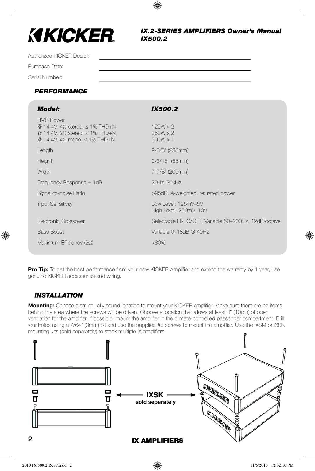
INSTALLATION
Mounting: Choose a structurally sound location to mount your KICKER amplifi er. Make sure there are no items behind the area where the screws will be driven. Choose a location that allows at least 4” (10cm) of open ventilation for the amplifi er. If possible, mount the amplifi er in the
IXSK
sold separately
2 | IX AMPLIFIERS |
2010 IX 500.2 RevF.indd 2
11/5/2010 12:32:10 PM