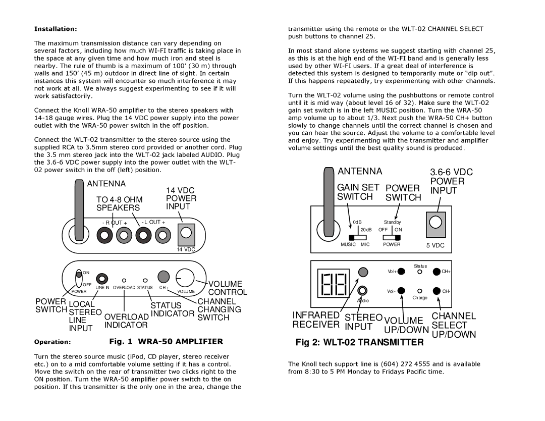
WRA-50 specifications
The Knoll Systems WRA-50 is an advanced wireless audio solution designed to meet the demands of modern users seeking flexibility and high-quality sound. This device is particularly suited for both residential and commercial audio applications, making it a versatile choice for various environments such as homes, offices, restaurants, and retail spaces.One of the standout features of the WRA-50 is its robust wireless connectivity. Utilizing state-of-the-art technologies, this device supports a variety of streaming options including Bluetooth, Wi-Fi, and AirPlay, providing users with multiple ways to connect their devices. This allows for seamless integration with smartphones, tablets, and computers, making it easy to access and control audio sources wirelessly.
The WRA-50 is equipped with high-definition audio capabilities that ensure crisp and clear sound reproduction. It supports various audio formats, enabling users to enjoy their favorite music in rich detail. The built-in high-performance DAC (Digital-to-Analog Converter) enhances audio quality further by reducing distortion and preserving the integrity of sound.
Another key characteristic of the WRA-50 is its user-friendly interface. The device features an intuitive control panel and a companion mobile app that allows for easy navigation and management of audio settings. These controls enable users to customize their listening experience by adjusting volume, balance, and EQ settings to suit personal preferences.
In addition to its impressive sound performance and connectivity options, the WRA-50 also boasts impressive versatility in its configuration. Users can easily set up a multi-room audio system, allowing for synchronized playback across multiple zones or rooms. This makes it an ideal choice for those looking to create an immersive audio environment in their home or business.
The design of the WRA-50 is another aspect worth mentioning. Its sleek and modern aesthetic, combined with durable construction, ensures that the device not only performs well but also looks good in any setting. Whether mounted on a wall or placed on a shelf, the device seamlessly blends into its environment.
Overall, the Knoll Systems WRA-50 is a powerful and flexible wireless audio solution that offers high-quality sound, advanced connectivity options, and user-friendly controls. Whether for personal use or commercial application, it stands out as a top choice for users seeking a reliable audio system that meets contemporary audio demands.

