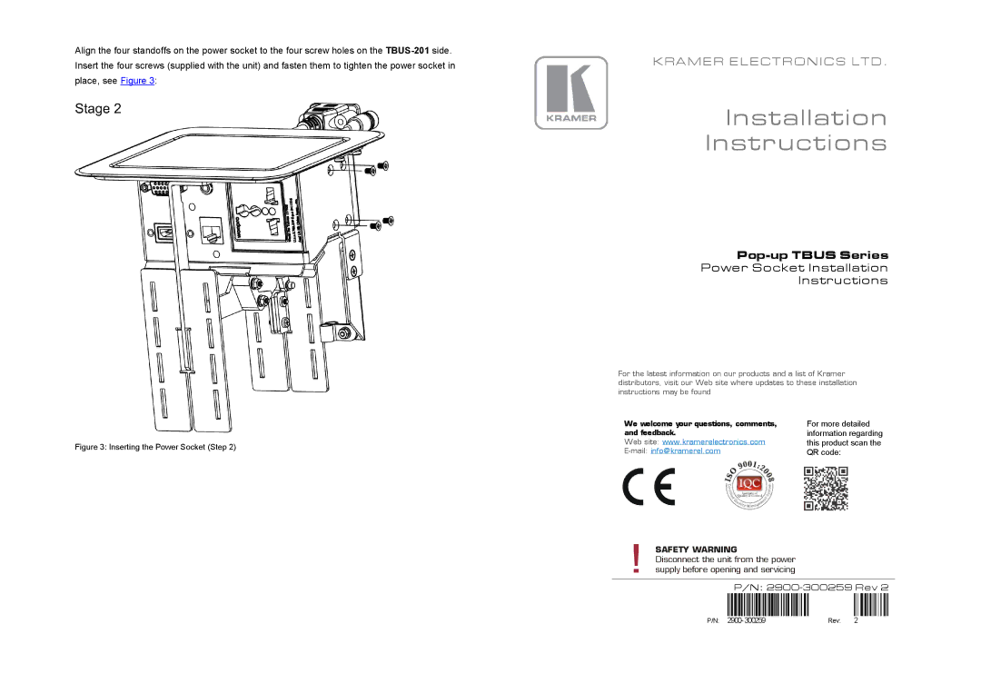
Align the four standoffs on the power socket to the four screw holes on the
Figure 3: Inserting the Power Socket (Step 2)
KRAMER ELECTRONICS LTD.
Installation
Instructions
Pop-up TBUS Series
Power Socket Installation
Instructions
For the latest information on our products and a list of Kramer distributors, visit our Web site where updates to these installation instructions may be found
We welcome your questions, comments, | For more detailed |
and feedback. | information regarding |
Web site: www.kramerelectronics.com | this product scan the |
QR code: |
!SAFETY WARNING
Disconnect the unit from the power supply before opening and servicing
P/N:
P/N: 2900- 300259 | Rev: | 2 |