Connecting the
5.2Wiring the CAT 5 LINE IN / LINE OUT RJ-45 Connectors
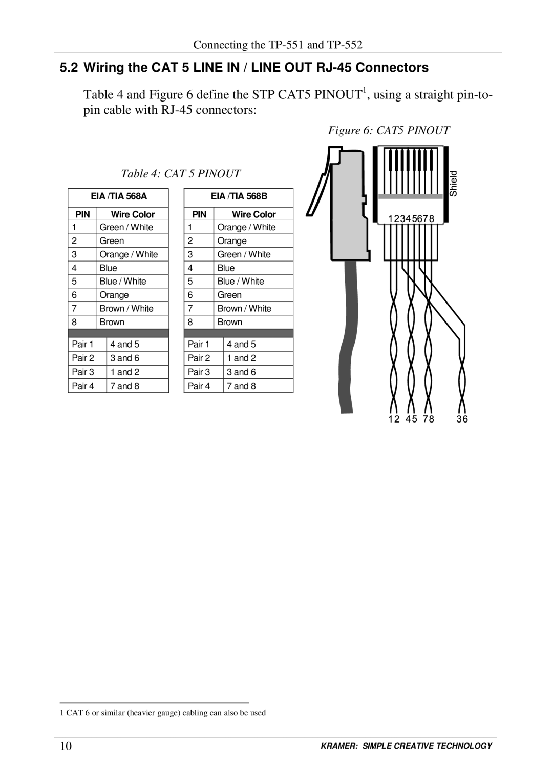
Table 4 and Figure 6 define the STP CAT5 PINOUT1, using a straight
Figure 6: CAT5 PINOUT
Table 4: CAT 5 PINOUT
EIA /TIA 568A | ||
|
|
|
PIN |
| Wire Color |
1 | Green / White | |
2 | Green | |
3 | Orange / White | |
4 | Blue | |
5 | Blue / White | |
6 | Orange | |
7 | Brown / White | |
8 | Brown | |
|
|
|
Pair 1 |
| 4 and 5 |
Pair 2 |
| 3 and 6 |
Pair 3 |
| 1 and 2 |
Pair 4 |
| 7 and 8 |
| EIA /TIA 568B | ||
|
|
|
|
PIN |
|
| Wire Color |
1 |
| Orange / White | |
2 |
| Orange | |
3 |
| Green / White | |
4 |
| Blue | |
5 |
| Blue / White | |
6 |
| Green | |
7 |
| Brown / White | |
8 |
| Brown | |
|
|
|
|
Pair 1 |
|
| 4 and 5 |
Pair 2 |
|
| 1 and 2 |
Pair 3 |
|
| 3 and 6 |
Pair 4 |
|
| 7 and 8 |
1 CAT 6 or similar (heavier gauge) cabling can also be used
10 | KRAMER: SIMPLE CREATIVE TECHNOLOGY |