C.The wire used to interconnect the solar modules may be single or two conductor, from 14 AWG (2.08 mm2) up to 10 AWG (5.26 mm2) gauge stranded copper wire, in a “SUNLIGHT RESISTANT” jacket UF cable. This cable is suitable for applications where wiring is exposed to the direct rays of the sun. The maximum and minimum outer diameters of the cable that may be used with the cable connector are 8 mm and 6 mm respectively (Fig. 3).
D.Using a flat blade screwdriver, remove only the appropriate
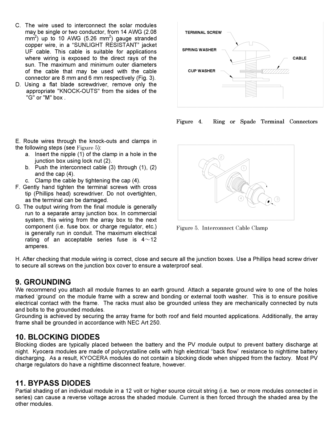
TERMINAL SCREW
SPRING WASHER
CABLE
CUP WASHER
E. Route wires through the
a.Insert the nipple (1) of the clamp in a hole in the junction box using lock nut (2).
b.Push the interconnect cable (3) through (1), (2) and the cap (4).
c.Clamp the cable by tightening the cap (4).
F.Gently hand tighten the terminal screws with cross tip (Phillips head) screwdriver. Do not overtighten, as the terminal can be damaged.
G.The output wiring from the final module is generally run to a separate array junction box. In commercial system, this wiring from the array box to the next component (i.e. fuse box. or charge regulator, etc.) is generally run in conduit. The maximum electrical rating of an acceptable series fuse is 4~12 amperes.
Figure 4. Ring or Spade Terminal Connectors
Figure 5. Interconnect Cable Clamp
H. After checking that module wiring is correct, close and secure all the junction boxes. Use a Phillips head screw driver to secure all screws on the junction box cover to ensure a waterproof seal.
9. GROUNDING
We recommend you attach all module frames to an earth ground. Attach a separate ground wire to one of the holes marked ‘ground’ on the module frame with a screw and bonding or external tooth washer. This is to ensure positive electrical contact with the frame. The racks must also be grounded unless they are mechanically connected by nuts and bolts to the grounded modules.
Grounding is achieved by securing the array frame for both roof and field mounted applications. Additionally, the array frame shall be grounded in accordance with NEC Art 250.
10. BLOCKING DIODES
Blocking diodes are typically placed between the battery and the PV module output to prevent battery discharge at night. Kyocera modules are made of polycrystalline cells with high electrical “back flow” resistance to nighttime battery discharging. As a result, KYOCERA modules do not contain a blocking diode when shipped from the factory. Most PV charge regulators do have a nighttime disconnect feature, however.
11. BYPASS DIODES
Partial shading of an individual module in a 12 volt or higher source circuit string (i.e. two or more modules connected in series) can cause a reverse voltage across the shaded module. Current is then forced through the shaded area by the other modules.