INSTALLATION MANUAL
FOR THE
KD135SX-UPU,KD140SX-UPU
OF
SOLAR PHOTOVOLTAIC POWER MODULES
Please read this manual carefully before installing the modules.
KYOCERA
1. INTRODUCTION
As the world leader in development and application of high technology ceramic/silica materials, Kyocera offers a wide range of highly efficient and reliable crystalline silicon solar photovoltaic (PV) power modules. Kyocera began to extensively research PV technology in 1975 and commenced manufacturing operations in 1978. Since then, Kyocera has supplied millions of cells and modules throughout the world. With years of experience and
2. POWER MODULES
Kyocera PV power modules consist of a series of electrically interconnected crystalline silicon solar cells, which are permanently laminated within a pottant and encapsulated between a tempered glass cover plate and a back sheet. The entire laminate is secured within an anodized aluminum frame for structural strength, ease of installation, and to protect the cells from the most severe environmental conditions.
3. APPLICATIONS
Kyocera PV modules are a reliable, virtually
4. WARNINGS & SAFETY
PV modules generate electricity when exposed to light. Arrays of many modules can cause lethal shock and burn hazards. Only authorized and trained personnel should have access to these modules. To reduce the risk of electrical shock or burns, PV modules may be covered with an opaque material during installation. Do not touch live terminals with bare hands. Use insulated tools for electrical connections. Do not use these PV modules for solar concentration.
WARNING
“SUITABLE FOR USE IN CLASS I, DIVISION 2, GROUPS A, B, C AND D HAZARDOUS LOCATIONS, OR NONHAZARDOUS LOCATIONS ONLY.”
“WARNING - EXPLOSION HAZARD - DO NOT DISCONNECT EQUIPMENT WHILE THE CIRCUIT IS LIVE OR UNLESS THE AREA IS KNOWN TO BE FREE OF IGNITABLE CONCENTRATIONS.”
“WARNING - EXPLOSION HAZARD - SUBSTITUTION OF ANY COMPONENT MAY IMPAIR SUITABILITY FOR CLASS I, DIVISION 2.”
PERMIT
・Before installing your PV system, contact local authorities to determine the necessary permitting, installation and inspection requirements.
INSTALLATION AND OPERATION
・Systems should be installed by qualified personnel only. The system involves electricity, and can be dangerous if the personnel are not familiar with the appropriate safety procedures.
・Do not step on a PV module.
・Although Kyocera PV modules are quite durable, the glass can
be broken (and PV module will no longer work properly) if it is dropped or hit by tools or other objects.
・PV module frame is made of anodized aluminum, and therefore corrosion can occur if PV module is subject to a
・KD series module frames must be attached to a support structure by one of the methods described in Section 7, Installing KD series modules.
・Module support structures to be used to support PV modules should be wind rated and approved by the appropriate local and civil codes prior to installation.
・Do not expose the back of PV module to direct sunlight.
・In Canada installation shall be in accordance with CSA C22.1, Safety Standard for Electrical Installations, Canadian Electrical Code, Part 1.
FIRE RATING
・In case of roof installation, PV module assembly shall be mounted on a fire resistant roof covering rated for the application. KD series modules are comprised of a glass front surface, polyethylene terephthalate (PET) back sheet with a Class C fire rating.
GROUNDING
・Refer to “Grounding” section.
BATTERY
・When PV modules are used to charge batteries, the battery must be installed in a manner which will ensure the performance of the system and the safety of its users. Follow the battery manufacturer’s safety guidelines concerning installation, operation and maintenance recommendations. In general, the battery (or battery bank) should be kept away from people and animals. Select a battery site that is protected from sunlight, rain, snow, debris, and is well ventilated. Most batteries generate hydrogen gas when charging, which can be explosive. Do not light matches or create sparks near the battery bank. When a battery is installed outdoors, it should be placed in an insulated and ventilated battery case specifically designed for this purpose.
5.SITE SELECTION
In most applications, Kyocera modules should be installed in a location where they will receive maximum sunlight throughout the year. In the Northern Hemisphere, the modules should typically face south, and in the Southern Hemisphere, the modules should typically face north. Modules facing 30 degrees away from true South (or North) will lose approximately 10 to 15 percent of their power output. If the module faces 60 degrees away from true South (or North), the power loss will be 20 to 30 percent. When choosing a site, avoid trees, buildings or obstructions which could cast shadows on PV modules especially during winter season when the arc of the sun is lowest over the horizon.
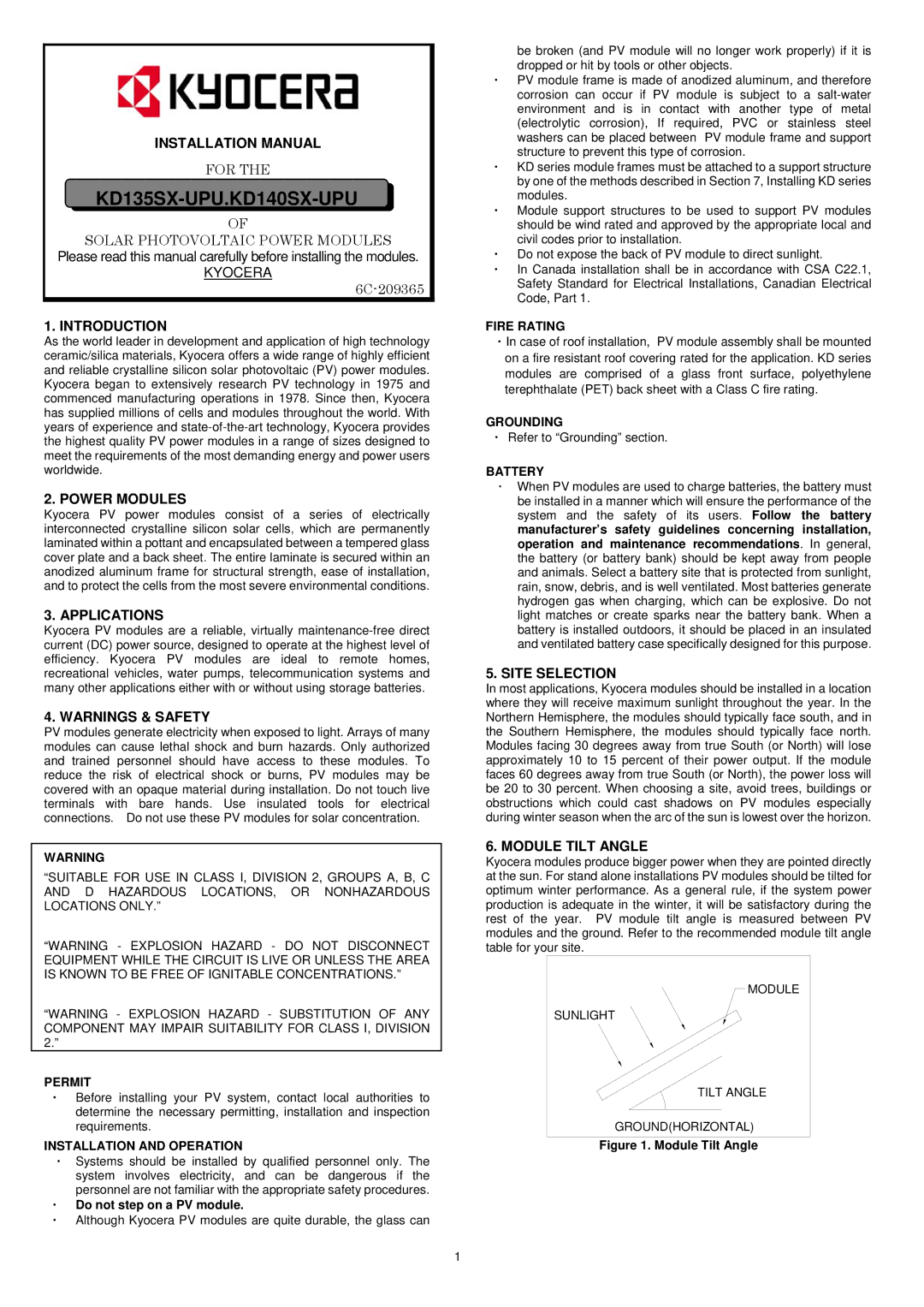
6. MODULE TILT ANGLE
Kyocera modules produce bigger power when they are pointed directly at the sun. For stand alone installations PV modules should be tilted for optimum winter performance. As a general rule, if the system power production is adequate in the winter, it will be satisfactory during the rest of the year. PV module tilt angle is measured between PV modules and the ground. Refer to the recommended module tilt angle table for your site.
MODULE
SUNLIGHT
TILT ANGLE
GROUND(HORIZONTAL)
Figure 1. Module Tilt Angle
1