High Rate Spring Kit
Assembly Instructions
| For All Treker Series | Manual No. | |
|
| ||
| Before You Start | Initial Preparations |
|
When you see this symbol, the subsequent
!instructions and warnings are serious - follow without exception. Your life and the lives of others depend on it!
1.Park vehicle on a flat surface, move gear shift lever to neutral or park, set park brake if available, turn off engine and remove ignition key.
2.Chock front and back side of rear wheels.
3.Loosen wheel lug nuts
IMPORTANT: Before you begin, read these instructions and check to be sure all parts and tools are accounted for. Please retain these installation instructions for future reference and parts ordering information.
Your High Rate Coil Springs are exclusively designed for your Land Pride Treker. Please read these installation instructions and your Treker Operator’s Manual thoroughly before beginning. Especially read information relating to safety concerns.
A separate Parts Manual for replacement parts can be purchased from your dealer or available free of charge at www.landpride.com. Have model and serial numbers handy when placing an order.
Manual Part Numbers:
4200NT/ST & 4400NT/ST Trekers
•Operator’s Manual . . . . . . . . . . . . . . . .
•Parts
4210ST & 4410ST Trekers
•Operator’s Manual . . . . . . . . . . . . . . . .
•Parts
4220ST & 4420ST Trekers
•Operator’s Manual . . . . . . . . . . . . . . . .
•Parts Manual . . . . . . . . . . . . . . . . . . . . .
General Information
These assembly instructions apply to the following High Rate Spring Kit listed below:
701-193A SPRINGS, ST TREKER HIGH RATE
It includes 2 Coil Springs Part Number
Tools required:
•Safety glasses, Work gloves & Tape Measure
•Spring compressing equipment
•9/16" & 14mm wrench
•Pliers or small vise grips
Assembly Instructions
Refer to your Operator’s Manual Maintenance Section for instructions on Securing Vehicle for Maintenance, Tire Maintenance and Jacking the Vehicle.
4.Refer to your Operator’s Manual for detailed instructions on jacking your vehicle. Place jack under the vehicle’s body frame close to where the right front
5.For safety, support the wheel off the ground by placing a jack stand under the body frame and then lowering the vehicle onto the jack stand.
6.Remove right front wheel from the vehicle.
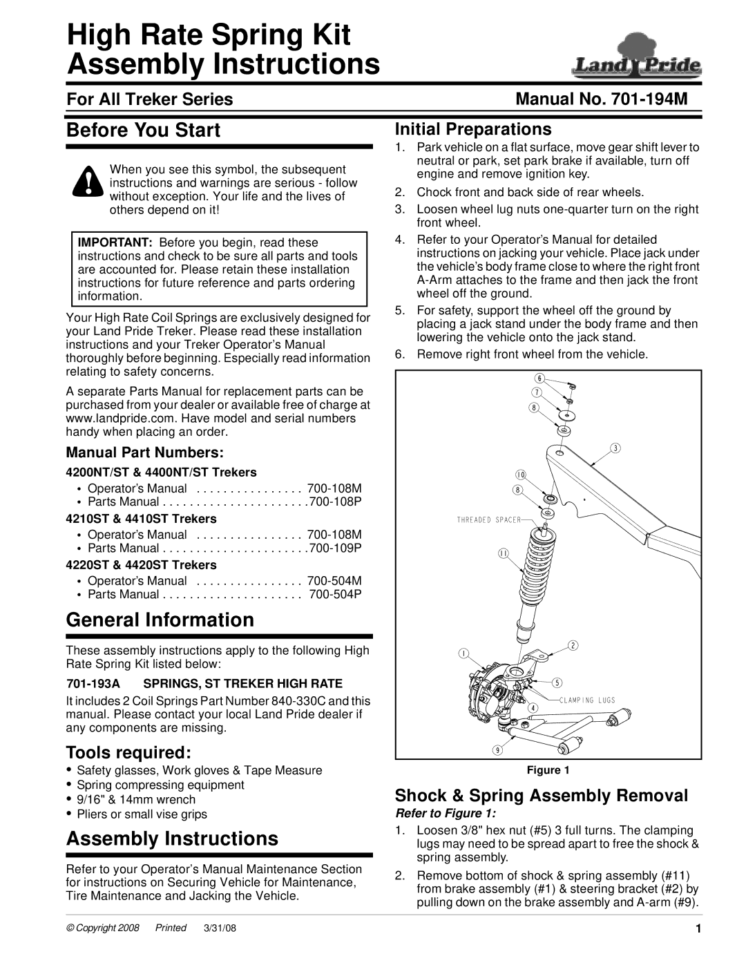
Figure 1
Shock & Spring Assembly Removal
Refer to Figure 1:
1.Loosen 3/8" hex nut (#5) 3 full turns. The clamping lugs may need to be spread apart to free the shock & spring assembly.
2.Remove bottom of shock & spring assembly (#11) from brake assembly (#1) & steering bracket (#2) by pulling down on the brake assembly and
© Copyright 2008 | Pr inted | 3/31/08 | 1 |