ST Back Screen
Assembly Instructions
| Treker ST 00 & 10 Series |
| Manual No. | ||
|
|
|
|
| |
|
|
|
|
| |
| Before You Start |
| Assembly Instructions | ||
|
|
|
|
|
|
When you see this symbol, the subsequent
!instructions and warnings are serious - follow without exception. Your life and the lives of others depend on it!
IMPORTANT: Before you begin, read these instructions and check to be sure all parts and tools are accounted for. Please retain these installation instructions for future reference and parts ordering information.
Your ST Back Screen is exclusively designed for your Land Pride ST Treker. Please read these installation instructions and your ST Treker Operator’s Manual thoroughly before beginning. Especially read information relating to safety concerns. Also included in the Operator’s Manual is important information on operation, adjustment, troubleshooting, and maintenance for this attachment (some manual sections do not apply to all accessories).
General Information
These assembly instructions apply to the following ST Back Screen Accessories listed below:
Further Assistance
Your dealer wants you to be satisfied with your new ST Back Screen. If for any reason you do not understand any part of this manual or are not satisfied with the service received, the following actions are suggested:
1.Discuss the matter with your dealership service manager making sure he is aware of any problems you may have and that he has had the opportunity to assist you.
2.If you are still not satisfied, seek out the owner or general manager of the dealership, explain the problem and request assistance.
3.For further assistance write to:
Land Pride Service Department
1525 East North Street
P.O. Box 5060
Salina, Ks.
lpservicedept@landpride.com
A detailed listing of parts for this accessory kit is provided on page 2. Use the list as a checklist to inventory parts received. Please contact your local Land Pride dealer for any missing hardware.
ALL DIRECTIONS REFERRING TO THE RIGHT AND LEFT ARE WHEN THE OPERATOR IS ON THE MACHINE.
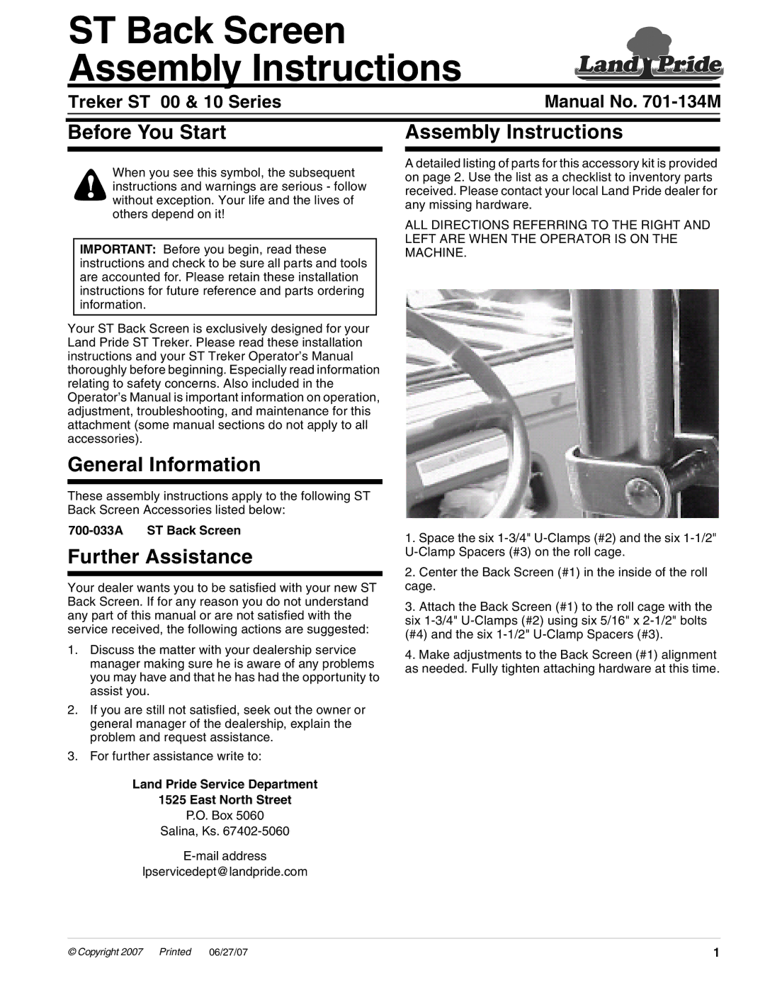
1.Space the six
2.Center the Back Screen (#1) in the inside of the roll cage.
3.Attach the Back Screen (#1) to the roll cage with the six
4.Make adjustments to the Back Screen (#1) alignment as needed. Fully tighten attaching hardware at this time.
© Copyright 2007 | Printed | 06/27/07 | 1 |