Down Pressure Kit
Assembly Instructions
RTA25, RTR25 & RTA35 Series Rotary Tillers | Manual No. | ||
|
|
|
|
Before You Start
When you see this symbol, the subsequent ! instructions and warnings are serious - follow
without exception. Your life and the lives of others depend on it!
IMPORTANT: Before you begin, read these instructions and check to be sure all parts and tools are accounted for. Please retain these installation instructions for future reference and parts ordering information.
Your Down Pressure Kit is exclusively designed for your Land Pride Rotary Tiller. Please read these installation instructions and your Rotary Tiller Operator’s Manual thoroughly before beginning. Especially read information relating to safety concerns. Also included in the Operator’s Manual is important information on operation, adjustment, troubleshooting, and maintenance for this attachment (some manual sections do not apply to all accessories).
A separate Parts Manual for replacement parts can be purchased from your dealer or available free of charge at www.landpride.com. Have model and serial numbers handy when placing an order.
Manual Part Numbers:
•RTA 25 Series Operator’s Manual . . . .
•RTA 35 Series Operator’s Manual . . . . .
•RTR 25 Series Operator’s Manual . . . . .
•Parts Manual (All Three
General Information
This assembly instructions apply to the following Down Pressure Kit listed below:
311-162 A Down Pressure Kit
A detailed listing of parts for this accessory kit is provided below. Use the list as a checklist to inventory parts received. Please contact your local Land Pride dealer for any missing hardware.
Your Kit Includes:
Qua. | Part No. | Part Description |
2 | SPRING ROD COLLAR RTA25/35 | |
2 | HHCS | |
2 | DOWN PRESSURE SPRING |
Assembly Instructions
Tools required:
•Safety glasses
•Work gloves
•9/16" box end or open end wrench
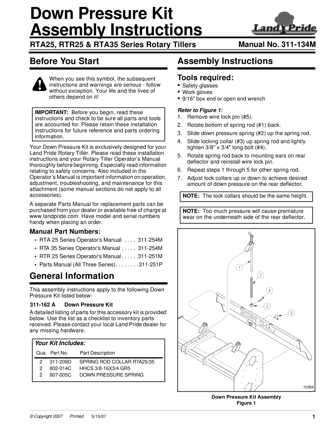
Refer to Figure 1:
1.Remove wire lock pin (#5).
2.Rotate bottom of spring rod (#1) back.
3.Slide down pressure spring (#2) up the spring rod.
4.Slide locking collar (#3) up spring rod and lightly tighten 3/8" x 3/4" long bolt (#4).
5.Rotate spring rod back to mounting ears on rear deflector and reinstall wire lock pin.
6.Repeat steps 1 through 5 for other spring rod.
7.Adjust lock collars up or down to achieve desired amount of down pressure on the rear deflector.
NOTE: The lock collars should be the same height.
NOTE: Too much pressure will cause premature wear on the underneath side of the rear deflector.
10364 |
Down Pressure Kit Assembly
Figure 1
© Copyright 2007 | Pr inted | 5/15/07 | 1 |