GENERAL SAFETY INFORMATION

When using electrical appliances, basic precautions should always be followed to reduce the risk of fire, elec-

trical shock and injury to persons, including the following:

Read all instructions before using this Fan.

1.Make certain the power source conforms to the electrical requirements of the Fan.

2.Make certain that the room is equipped with a working smoke detector.

3.Use this Fan only as described in this manual. Any other use not recommended by the manufacturer may cause fire, electrical shock, or injury to persons.

4.To reduce the risk of personal injury and electric shock, the Fan should not be played with or placed where small children can reach it.

5.Unplug power cord before installing, servicing, or moving the Fan.

DO NOT DEPEND ON THE ON/OFF SWITCH AS THE SOLE MEANS OF DISCONNECTING POWER WHEN SERVICING OR MOVING THE FAN. ALWAYS UNPLUG THE POWER CORD. ALWAYS TURN OFF AND UNPLUG FAN BEFORE LEAVING THE AREA. NEVER LEAVE CHILDREN UNATTENDED WHEN THE FAN IS ON OR PLUGGED IN.

6.This Fan must NOT be used in potentially dangerous locations such as flammable, explosive, chemical-laden or wet atmospheres where gasoline, paint or flammable liquids are used or stored.

7.DO NOT use Fan in or near a window. Rain may create an electrical hazard.

8.Completely assemble Fan, according to instructions, before connecting to power supply.

This appliance has a polarized plug (one blade is wider than the other). To reduce the risk of electric shock, this plug is intended to fit in a polarized outlet only one way. Match wide blade of plug to wide slot. Fully insert. If the plug does not fit fully in the outlet, reverse the plug. If it still does not fit, contact a qualified electrician. DO NOT attempt to defeat this safety feature. This plug is a safety feature, to reduce the risk of fire, electric shock and personal injury. DO NOT remove, replace, repair or tamper with the originally supplied plug. If the Fan does not function properly, it may be due to the safety device incorporated in this plug. Return to an authorized service center or call 800-233-0268, Monday - Friday, between 8:00 a.m. and 5:00 p.m. EST. If the plug warning label is missing or damaged, call the toll free number for a replacement label.

9.Where possible, avoid the use of extension cords because the extension cord may overheat and cause a fire. If you must use an extension cord, minimize the risk of overheating by using the shortest cord possible and ensuring that it is UL listed. NEVER use a single extension cord to operate more than one Fan. Do not plug Fan into any other cord connected device, such as a power strip, cord reel, surge protector, multiple outlet adapters or outlet-type air fresheners. The use of such devices may create a fire hazard.

10.NEVER operate any Fan with a damaged cord or plug or after the Fan malfunctions, has been dropped or damaged in any manner. There are no user serviceable parts. Return Fan to an authorized service facility for examination, electrical or mechanical adjustment or repair.

11.NEVER insert or allow fingers or foreign objects to enter any ventilation or exhaust opening as it may cause an electric shock or fire, or damage the Fan. To reduce the risk of fire, DO NOT block or tamper with the Fan in any manner while it is in operation.

12.Always place the Fan on a stable, flat, level surface when operating, to avoid the chance of the Fan overturning. Locate the Power Cord so the Fan or other objects are not resting on it. DO NOT run Power Cord under carpeting. DO NOT cover Power Cord with throw rugs, runners or the like. Arrange Power Cord away from room traffic and where it will not be tripped over.

13.This Fan is not intended for use in wet or damp locations. Never locate a Fan where it may fall into a bathtub or other water container. NEVER use Fan where flammable liquids are used or stored.

14.NEVER use Fan outdoors.

15.Remote controls for other appliances or electronic equipment can sometimes interfere with the operation of this Fan. If this occurs, move the fan to another location.

16.Keep Fan remote unit away from chairs and your bed where it may be sat or laid upon and inadvertently turn on the Fan.

17.This Fan is not suitable for use in agricultural facilities including areas where livestock, poultry or other animals are confined. Please refer to National Electric Code (NEC) Article 547-7 (2008), or ap- plicable state or local codes or standards relating to electrical requirements for Agricultural Buildings. THIS FAN DOES NOT MEET THE REQUIRMENTS OF NEC ARTICLE 547-7 (2008).

18.This Fan is not suitable for use in hazardous locations. Please refer to National Electric Code (NEC) Article 500 or applicable state or local codes or standards relating to electrical requirements for Hazardous locations. THIS FAN DOES NOT MEET THE REQUIRMENTS OF NEC ARTICLE 500 (2008).

REDUCE THE RISK OF FIRE OR ELECTRIC SHOCK - DO NOT USE THIS FAN WITH ANY SOLID STATE

SPEED CONTROL DEVICES.

SAVE THESE INSTRUCTIONS

INFORMACIÓN GENERAL DE SEGURIDAD

Al usar artefactos eléctricos, siempre deben tomarse precauciones básicas para reducir el riesgo de incendio,

choque eléctrico y lesiones a personas, incluyendo las siguientes:

Lea todas las instrucciones antes de usar este Ventilador.

1.Asegúrese que la fuente de alimentación coincida con los requerimientos eléctricos del Ventilador.

2.Asegúrese que la habitación esté equipada con un detector de humo en funcionamiento.

3.Use este Ventilador únicamente como se describe en este manual. Cualquier otro uso no recomendado por el fabricante puede causar incendio, choque eléctrico o lesiones a personas.

4.Para reducir el riesgo de lesiones a personas y choque eléctrico, el Ventilador no debe ser encendido o colocado donde los niños pequeños puedan alcanzarlo.

5.Desconecte el cable eléctrico antes de instalar, reparar o trasladar el Ventilador.

NO DEPENDA DEL INTERRUPTOR DE ENCENDIDO / APAGADO COMO ÚNICO MEDIO DE DESCONECTAR LA ALIMENTACIÓN ELÉCTRICA CUANDO ESTÉ REPARANDO O TRASLADANDO EL VENTILADOR. SIEMPRE DESCONECTE EL CABLE ELÉCTRICO. SIEMPRE APAGUE Y DESCONECTE EL VENTILADOR ANTES DE ABANDONAR EL ÁREA. NUNCA DEJE A LOS NIÑOS SIN ATENCIÓN CUANDO EL VENTILADOR ESTÉ ENCENDIDO O CONECTADO.

6.

Este Ventilador NO debe ser usado en lugares potencialmente peligrosos tales como atmósferas inflamables, explosivas, cargadas de sustancias químicas o húmedas donde se usen o almacenen gasolina,

7.

pintura o líquidos inflamables.

NO use el Ventilador dentro de o cerca de una ventana. La lluvia podría crear un riesgo eléctrico.

1.Take pipe assembly out of carton as shown. (Figure 1) Saque el conjunto de la tubería del cartón como muestra. (Figura 1)

2.Loosen Height Adjustment Nut turning counter clockwise. (Figure 2) Desafloje la Tuerca de Ajuste de Altura, girando en sentido contrahorario. (Figura 2)

3.Raise Extension Pipe. (Figure 3)

Eleve la Extensión De La Tubería. (Figura 3)

4.Tighten Height Adjustment Nut turning clockwise. (Figure 4)

Apriete la Tuerca de Ajuste de Altura, girando en sentido horario. (Figura 4)


Extension Pipe


Tubería de


Extension


Height Adjustment


Nut


Tuerca de Ajuste de


Altura


Figure 1

Figure 2

Figure 3

Figure 4

Figura 1

Figura 2

Figura 3

Figura 4

1. With a twisting motion, insert the end of the large

Extension Pipe

Tubo de

diameter pipe into hole in Base. (Figure 5) Turning

Extensión


pipe while pushing will assure pipe is fully seated in


Base.


Utilizando un movimiento giratorio, inserte el extremo

Height


del tubo de diámetro grande en el agujero de la Base.

Adjustment Nut


(Figura 5) El girar el tubo a medida que se lo empuja


asegura que el tubo quede plenamente asentado en

Tuerca de Ajuste


la Base.


de Altura


2. For Height Adjustment:


a) Loosen Height Adjustment Nut.


b) Raise or lower Extension Pipe to


desired height.


Base


c) Tighten Height Adjustment Nut.


Para ajustar la altura:


a)Afloje la Tuerca de Ajuste de Altura.

b)Eleve o baje el Tubo de Extensión hasta obtener la altura deseada.

c) Apriete la Tuerca de Ajuste de Altura.

Figure 5

Figura 5


Head


Assembly


1.

Place Head Assembly with Collar onto

Conjunto de


Cabezal


Extension Pipe. (Figure 6)


Coloque el Conjunto de Cabezal

con


el Collar en el Tubo de Extensión. (Figura 6)


2.

Holding Extension Pipe firmly,

twist


Head Assembly downwarduntil seated


on Extension Pipe.


Collar


Sostenga firmemente el Tubo de Exten-


sión y empuje el Conjunto de Cabezal


hacia abajo con un movimiento giratorio


hasta que quede asentado en el Tubo


de Extensión.


Extension


Pipe


Figure 6

Tubo de

Figura 6


Extensión

1.

Tilt Head Assembly back. Put


Figure 7

Figura 7


Rear Grill on Motor. (Figure 7)


Rear


Inclinarla Cabeza del Ventilador


Grill


Motor


hacia atrás. Coloque la Rejilla


Trasera en el Motor. (Figura 7)


Rejilla


2.

Align tab of Plastic Rear Grill

Trasera


with groove on top of front


Motor cover.


Alinear la lengüeta de la Rejilla


Trasera con la ranura en la parte


superior de la cubierta delantera


del Motor.


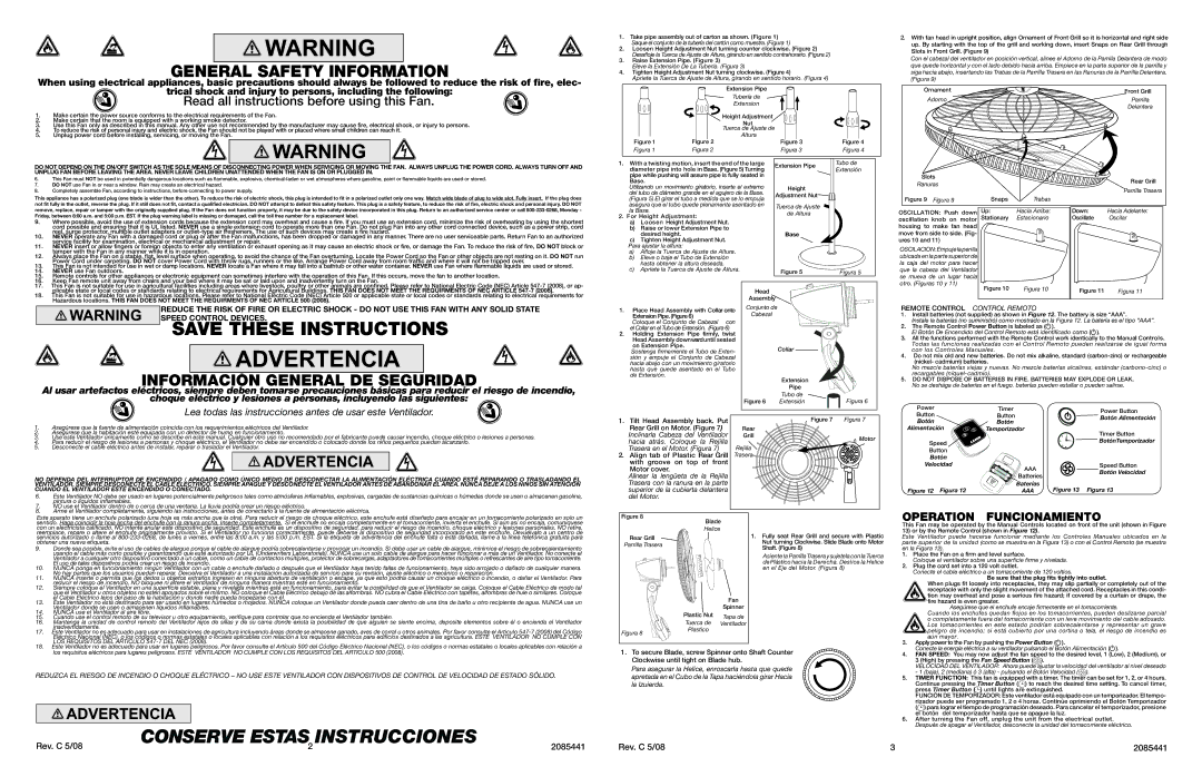
2.With fan head in upright position, align Ornament of Front Grill so it is horizontal and right side up. By starting with the top of the grill and working down, insert Snaps on Rear Grill through Slots in Front Grill. (Figure 9)

Con el cabezal del ventilador en posición vertical, alinee el Adorno de la Parrilla Delantera de modo que quede horizontal y con el lado debido hacia arriba. Empiece en la parte superior de la parrilla y siga hacia abajo, insertando las Trabas de la Parrilla Trasera en las Ranuras de la Parrilla Delantera. (Figura 9)

Ornament

Front Grill

Adorno

Parrilla


Delantera

Slots

Rear Grill

Ranuras

Parrilla Trasera


Figure 9

Figura 9

Snaps

Trabas


OSCILLATION: Push down

Up:

Hacia Arriba:

Down:

Hacia Adelante:

oscillation

knob on motor

Stationary

Estacionario

Oscillate

Oscilar

housing to make fan head


move from side to side. (Fig-


ures 10 and 11)


OSCILACION:Empuje la perilla


ubicada en la parte superior de


la caja del motor para hacer


que la cabeza del Ventilador


se mueva de un lugar hacia


otro. (Figuras 10 y 11)

Figure 10

Figura 10


Figure 11

Figura 11


REMOTE CONTROL CONTROL REMOTO

1.Install batteries (not supplied) as shown in Figure 12. The battery is size “AAA”.

Instale la baterías (no suministró) como mostrado en la Figura 12. La batería es el tipo “AAA”.

2.The Remote Control Power Button is labeled as ( ).

El Botón De Encendido del Control Remoto está identificado como ( ).

3.All the functions performed with the Remote Control work identically to the Manual Controls. Todas las funciones realizadas con el Control Remoto pueden realizarse de igual forma con los Controles Manuales.

4.Do not mix old and new batteries. Do not mix alkaline, standard (carbon-zinc) or rechargeable (nickel- cadmium) batteries.

No mezcle baterías viejas y nuevas. No mezcle baterías alcalinas, estándar (carbono-cinc) o recargables (níquel-cadmio).

5.DO NOT DISPOSE OF BATTERIES IN FIRE. BATTERIES MAY EXPLODE OR LEAK. No se deshága de baterías en el fuego. baterías pueden estallar o pueden salirse.

Power

Timer

Power Button

Button

Button

Botón Alimentación

Botón

Botón


Alimentación

Temporizador

Timer Button


Speed


BotónTemporizador


Button


Botón


Velocidad

AAA

Speed Button


Botón Velocidad


Batteries


Figure 12 Figura 12

Baterías

Figure 13 Figura 13

AAA

8.

Arme el Ventilador completamente, siguiendo las instrucciones, antes de conectarlo a la fuente de alimentación eléctrica.

Este aparato tiene un enchufe polarizado (una hoja es más ancha que la otra). Para reducir el riesgo de choque eléctrico, este enchufe está diseñado para encajar en un tomacorriente polarizado en solo un sentido. Haga coincidir la hoja ancha del enchufe con la ranura ancha. Inserte completamente. Si el enchufe no encaja completamente en el tomacorriente, invierta el enchufe. Si aún así no encaja, comuníquese con un electricista calificado. NO intente anular este dispositivo de seguridad. Este enchufe es un dispositivo de seguridad, para reducir el riesgo de incendio, choque eléctrico y lesiones personales. NO retire, reemplace, repare o altere el enchufe originalmente provisto. Si el Ventilador no funciona correctamente, puede deberse al dispositivo de seguridad incorporado en este enchufe. Devuélvalo a un centro de servicios autorizado o llame al 800-233-0268, de lunes a viernes, entre las 8:00 a.m. y las 5:00 p.m. EST. Si la etiqueta de advertencia del enchufe falta o está dañada, llame a la línea telefónica gratuita para obtener una nueva etiqueta.

9.

Donde sea posible, evite el uso de cables de alargue porque el cable de alargue podría sobrecalentarse y provocar un incendio. Si debe usar un cable de alargue, minimice el riesgo de sobrecalentamiento


usando el cable más corto posible y garantizando que esté autorizado por UL (Underwriters Laboratories). NUNCA use un solo cable de alargue para hacer funcionar a más de un Ventilador. No conecte el


Ventilador a cualquier otro dispositivo conectado a un cable, como un cable de contactos múltiples, protector de sobrecargas, adaptadores de tomacorrientes múltiples o refrescantes de aire tipo tomacorriente.

10.

El uso de tales dispositivos podría crear un riesgo de incendio.

NUNCA ponga en funcionamiento ningún Ventilador con un cable o enchufe dañado o después que el Ventilador haya tenido fallas de funcionamiento, haya sido arrojado o dañado de cualquier manera.

11.

No hay partes que los usuarios puedan reparar. Devuelva el Ventilador a una instalación autorizada de servicio para su revisión, ajuste eléctrico o mecánico o reparación.

NUNCA inserte o permita que los dedos u objetos extraños ingresen en ninguna abertura de ventilación o escape, ya que esto podría causar un choque eléctrico o incendio, o dañar el Ventilador. Para

12.

reducir el riesgo de incendio, NO bloquee ni altere el Ventilador de ninguna manera mientras esté en funcionamiento.

Siempre coloque el Ventilador en una superficie estable, plana y nivelada mientras esté en funcionamiento, para evitar la posibilidad de que el Ventilador se caiga. Coloque el Cable Eléctrico de modo tal


que el Ventilador u otros objetos no estén apoyados sobre el mismo. NO coloque el Cable Eléctrico debajo de las alfombras. NO cubra el Cable Eléctrico con tapetes, alfombras de hule o similares. Coloque

13.

el Cable Eléctrico lejos del paso de la habitación y donde nadie pueda tropezarse con él.

Este Ventilador no está destinado para ser usado en lugares húmedos o mojados. Nunca coloque un Ventilador donde pueda caer dentro de una tina de baño u otro recipiente de agua. NUNCA use un

14.

Ventilador donde se usen o almacenen líquidos inflamables.

NUNCA use el Ventilador al aire libre.

15.

Cuando use el control remoto de su televisor u otro equipamiento, verifique para controlar que no encienda el Ventilador también.

16.

Mantenga la unidad de control remoto del Ventilador lejos de sillas y de su cama donde exista la posibilidad de que alguien se siente encima, deposite elementos sobre él o encienda el Ventilador

17.

inadvertidamente.

Este Ventilador no es adecuado para usar en instalaciones de agricultura incluyendo áreas donde se almacene ganado, aves de corral u otros animales. Por favor consulte el Articulo 547-7 (2008) del Código


Eléctrico Nacional (NEC), o los códigos o normas estatales o locales aplicables con relación a los requisitos eléctricos para edificios destinados a las agricultura. ESTE VENTILADOR NO CUMPLE CON

Figure 8

Blade


Helice

Rear Grill


Parrilla Trasera


Fan


Spinner


Plastic Nut

Tapa de


Tuerca de Ventilador

Figura 8

Plastico


1.Fully seat Rear Grill and secure with Plastic Nut turning Clockwise. Slide Blade onto Motor Shaft. (Figure 8)

Asiente la Parrilla Trasera y sujetela con la Tuerca de Plástico hacia la Derecha. Deslice la Helice en el Eje del Motor. (Figura 8)

OPERATION FUNCIONAMIENTO

This Fan may be operated by the Manual Controls located on front of the unit (shown in Figure 13) or by the Remote Control (shown in Figure 12).

Este Ventilador puede hacerse funcionar mediante los Controles Manuales ubicados en la parte superior de la unidad (como se muestra en la Figura 13) o con el Control Remoto (se muestra en la Figura 12).

1.Place the Fan on a firm and level surface.

Coloque el ventilador sobre una superficie firme y nivelada.

2.Plug the cord set into a 120 volt outlet.

Conecte el cable eléctrico a un tomacorriente de 120 voltios.

Be sure that the plug fits tightly into outlet.

When plugs fit loosely into receptacles, they may slip partially or completely out of the receptacle with only the slight movement of the attached cord. Receptacles in this condi- tion may overheat and pose a serious fire hazard; if covered by a curtain or drape, the fire hazard is even greater.

Asegúrese que el enchufe encaje firmemente en el tomacorriente.

Cuando los enchufes quedan flojos en los tomacorrientes, pueden deslizarse parcial o completamente fuera del tomacorriente con un leve movimiento del cable adosado. Los tomacorrientes en este estado podrían sobrecalentarse y representar un grave peligro de incendio; si está cubierto por una cortina o tela, el riesgo de incendio es aún mayor.

LOS REQUISITOS DEL ARTICULO 547-7 DEL NEC (2008).

18. Este Ventilador no es adecuado para usar en lugares peligrosos. Por favor consulte el Artículo 500 del Código Eléctrico Nacional (NEC), o los códigos o normas estatales o locales aplicables con relación a

los requisitos eléctricos para lugares peligrosos. ESTE VENTILADOR NO CUMPLE CON LOS REQUISITOS DEL ARTICULO 500 (2008).

REDUZCA EL RIESGO DE INCENDIO O CHOQUE ELÉCTRICO – NO USE ESTE VENTILADOR CON DISPOSITIVOS DE CONTROL DE VELOCIDAD DE ESTADO SÓLIDO.

1.To secure Blade, screw Spinner onto Shaft Counter Clockwise until tight on Blade hub.

Para asegurar la Helice, enroscarla hasta que quede apretada en el Cubo de la Tapa haciéndola girar Hacia la Izuierda.

3.Apply power to the Fan by pushing the Power Button ( ).

Conecte la energía eléctrica a su ventilador pulsando el Botón Alimentación ( ).

4.FAN SPEED: You may now adjust the fan speed to the desired level, 1 (Low), 2 (Medium), or

3 (High) by pressing the Fan Speed Button ( ).

VELOCIDAD DEL VENTILADOR: Ahora puede ajustar la velocidad del ventilador al nivel deseado - 1 (baja), 2 (mediana) ó 3 (alta) - pulsando el Botón Velocidad ( ).

5.TIMER FUNCTION: This fan is equipped with a timer. The timer can be set for 1, 2, or 4 hours. Continue pressing the Timer Button ( ) to reach the desired time setting. To cancel timer, press Timer Button ( ) until lights are extinguished.

FUNCIÓN DE TEMPORIZADOR: Este ventilador está equipado con un temporizador. El tempo- rizador puede ser programado 1, 2 o 4 horas. Continúe oprimiendo el Botón Temporizador ( ) para lograr el tiempo de programación deseado. Para cancelar el temporizador, presione el botón del temporizador hasta que se apague la luz.

6.After turning the Fan off, unplug the unit from the electrical outlet. Después de apagar el Ventilador, desconecte la unidad del tomacorriente eléctrico.

Rev. C 5/08

3

2085441

Page 2
Image 2
Lasko 1850W warranty Base, Be sure that the plug fits tightly into outlet

1850W specifications

The Lasko 1850W is a powerful and efficient ceramic space heater designed to provide consistent warmth and comfort in a variety of settings. With its sleek and modern design, this heater appears both functional and stylish, making it a perfect addition to any room.

One of the standout features of the Lasko 1850W is its innovative ceramic heating technology. This technology allows the heater to quickly warm up the surrounding area, ensuring prompt relief from the cold. Ceramic heaters are known for their ability to retain heat longer, which means they continue to provide warmth even after the unit has been turned off.

The Lasko 1850W boasts a powerful 1500-watt heating capability, making it suitable for heating medium to large rooms. The adjustable thermostat allows users to set the desired temperature, providing personalized comfort. Additionally, the heater offers two heat settings: high and low, enabling flexibility based on user preferences and room size.

Safety is a priority with the Lasko 1850W. It comes equipped with an overheat protection feature that automatically shuts off the unit if it gets too hot, preventing potential accidents. The heater also has a cool-touch exterior, which ensures that the outer surface remains safe to touch even during operation, making it a great choice for households with children or pets.

Portability is another significant aspect of the Lasko 1850W. The heater features a lightweight design and built-in handle, allowing users to easily move it from room to room as needed. This makes it ideal for use in various areas of the home, including bedrooms, living rooms, and offices.

The Lasko 1850W is designed for user-friendly operation. It includes a simple control panel, enabling quick adjustments to heat settings and overall functionality. Furthermore, its compact size means it can be placed inconspicuously in any corner without taking up too much space.

In summary, the Lasko 1850W combines efficient ceramic heating technology with a range of safety features and user-friendly design, making it an excellent choice for anyone seeking a reliable space heater. Whether used in a bedroom, office, or living space, the Lasko 1850W ensures that you stay warm and comfortable throughout the colder months.