MODELO 2265QM
GENERAL SAFETY INFORMATION
When using electrical appliances, basic precautions should always be followed to reduce
the risk of fire, electrical shock and injury to persons, including the following:
Read all instructions before using this Fan. 
1.Make certain the power source conforms to the electrical requirements of the Fan.
2.Make certain that the room is equipped with a working smoke detector.
3.Use this Fan only as described in this manual. Any other use not recommended by the manufacturer may cause fire, electrical shock, or injury to persons.
4.To reduce the risk of personal injury and electric shock, the Fan should not be played with or placed where small children can reach it.
5.Unplug power cord before installing, servicing, or moving the Fan.
DO NOT DEPEND ON THE ON/OFF SWITCH AS THE SOLE MEANS OF DISCONNECTING POWER WHEN SERVICING OR MOVING THE FAN. ALWAYS UNPLUG THE POWER CORD. ALWAYS TURN OFF AND UNPLUG FAN BEFORE LEAVING THE AREA. NEVER LEAVE CHILDREN UNATTENDED WHEN THE FAN IS ON OR PLUGGED IN.
6.This Fan must NOT be used in potentially dangerous locations such as flammable, explosive,
7.DO NOT use Fan in or near a window. Rain may create an electrical hazard.
8.Completely assemble Fan, according to instructions, before connecting to power supply.
The power cord is equipped with a
qualified electrician, using copper wire only.
This plug is a safety feature. It contains a safety device (fuse) that should not be removed. Discard product if the attach- ment plug is damaged. To reduce the risk of fire, electric shock and personal injury, DO NOT remove, replace, repair or tamper with the originally supplied plug. If the Fan does not function properly, it may be due to the safety device incorporated in this plug.
9.Where possible, avoid the use of extension cords because the extension cord may overheat and cause a fire. If you must use an exten- sion cord, minimize the risk of overheating by using the shortest cord possible and ensuring that it is UL listed. NEVER use a single extension cord to operate more than one Fan. Do not plug Fan into any other cord connected device, such as a power strip, cord reel, surge protector, multiple outlet adapters or
10.NEVER operate any Fan with a damaged cord or plug or after the Fan malfunctions, has been dropped or damaged in any manner.
11.NEVER insert or allow fingers or foreign objects to enter any ventilation or exhaust opening as it may cause an electric shock or fire, or damage the Fan. To reduce the risk of fire, DO NOT block or tamper with the Fan in any manner while it is in operation.
12.Always place the Fan on a stable, flat, level surface when operating, to avoid the chance of the Fan overturning. Locate the Power Cord so the Fan or other objects are not resting on it.Do not run cord under carpeting. Do not cover cord with throw rugs, runners, or similar coverings. Do not route cord under furniture or appliances. Arrange cord away from traffic area and where it will not be tripped over.
13.This Fan is not intended for use in wet or damp locations. Never locate a Fan where it may fall into a bathtub or other water con- tainer. NEVER use Fan where flammable liquids are used or stored.
14.NEVER use Fan outdoors.
15.This Fan is not suitable for use in agricultural facilities including areas where livestock, poultry or other animals are confined. Please refer to National Electric Code (NEC) Article
16.This Fan is not suitable for use in hazardous locations. Please refer to National Electric Code (NEC) Article 500 or applicable state or local codes or standards relating to electrical requirements for Hazardous locations. THIS FAN DOES NOT MEET THE REQUIRE-
MENTS OF NEC ARTICLE 500 (2008).
REDUCE THE RISK OF FIRE OR ELECTRIC SHOCK - DO NOT USE THIS FAN
WITH ANY SOLID STATE SPEED CONTROL DEVICES.
SAVE THESE INSTRUCTIONS
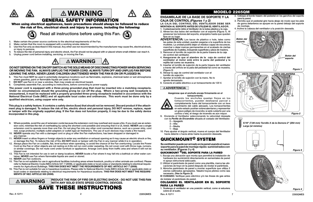
ENSAMBLAJE DE LA BASE DE SOPORTE Y LA CAJA DE Control (Figuras 1 y 2)
La caja del control del ventilador debe ser
montada al soporte antes de utilizar el Ventilador. 1. Cuidadosamente retire el Ventilador de la bolsa plástica y la caja.
2. Alinee los dos lados del ventilador con el soporte (Figura 1). Al presionar los botones del soporte, empújelos hasta que queden fijos en su lugar.
ADVERTENCIA: Los tacos de plástico o hule, tales como las patas de esta unidad, pueden pegarse a la superficie de los muebles. La unidad podría dejar un residuo capaz de oscurecer, manchar o dejar marcas permanentes en el acabado de ciertas superficies de muebles, incluyendo superficies y pisos de madera.
3.Remover el tornillo de sujeción de la parte trasera de la caja de control del ventilador.
4.Asegurarse de que el alambre de la caja de control del ventilador al motor está entre la parta del pedestal y la rejilla tal como se muestra.
5.Insertar el tornillo de sujeción de la parte trasera del ventilador a travez del orificio en la pata del pedestal tal como se muestra. (Figura 2)
6.Alinear la caja de control del ventilador con el tornillo de sujeción.
7.Apretar el tornillo de sujeción con la mano. No lo aprete demasiado.
8.Conecte el cable eléctrico a un tomacorriente de 120 V.
Asegúrese que el enchufe encaje firmemente en el
tomacorriente.
Cuando los enchufes quedan flojos en los tomacorrientes, pueden deslizarse parcial o completamente fuera del tomacorriente con un leve movimiento del cable adosado. Los tomacorrientes en este estado podrían sobrecalentarse y representar un grave peligro de incendio; si está cubierto por una cortina o tela, el riesgo de incendio es aún mayor.
9.Encienda el Ventilador seleccionando la velocidad deseada con la Perilla de Encendido situada al costado del Ventilador.
0– Apagado
3– Alta
2– Media
1– Baja
10.Para ajustar el ángulo vertical, mueva el cuerpo del Ventilador hacia delante o hacia atrás hasta la posición deseada.
QUICKMOUNT® SYSTEM
Su ventilador puede ser armado en la pared usando el nuevo soporte para la paed de montaje rápido suministrados con su ventilador. (Figuras 3 y 4)
QuickMount ®DEL SOPORTE PARA LA PARED
1.Escoja una ubicación que monta que permitirá la instalación de hardware (no suministró) directamente en sementales de pared ni apoyo estructural adecuado.
2.Utilizar el paréntesis de pared como una plantilla, marca las ubi- caciones de hoyo en la pared después de nivelar el paréntesis.
3.Abroche paréntesis de pared a montar superficie que utiliza 2
cierres calibrados apropiados. Taladre hoyos pilotos como sea necesario. (Vea la Figura 3).
El CUIDADO: Verifique para eléctrico y/o las líneas de gas antes de instalar el paréntesis de pared.
COLGANDO EL VENTILADOR EN EL SOPORTE PARA LA PARED
1.Sostenga el ventilador en una posición vertical, como si estuviera sobre en el suelo.
2.Coloque el borde trasero del pedestal en los ganchos del soporte para la pared.
3.Permita que el pedestal gire hacia abajo de modo que los pies de goma delanteros se apoyen en la pared debajo del soporte de montaje.
4.Incline la cabeza del ventilador a la posición deseada.
Botón del soporte
Botón del ![]() soporte
soporte
Figura 1
VISTA TRASERA | VISTA DELANTERA |
Figura 2
5/16" (7,94 mm) Tornillo X de la Demora 2" (254 mm) Largo (el mínimo)
Figura 3
Figura 4
Rev. A 12/11 | 2 | 2265QMES |
Rev. A 12/11 | 7 | 2265QMES |