MAINTENANCE
CLEANING: Disconnect from power outlet.
DO NOT IMMERSE FAN IN WATER. Use a soft cloth moistened with mild soap solution to clean fan parts.
Avoid the use of gasoline, benzine, thinner, harsh cleaners, etc. This will result in damage to the material.
Dry all parts thoroughly with a soft cloth before completely reassembling and reconnecting to power supply.
STORAGE: When not in use, keep unit in a clean dry place.
LUBRICATION: Precision bearings are sealed at the factory for life and do not require further lubrication.
TOOLS REQUIRED FOR ASSEMBLY
•2 Adjustable Wrenches (min 3/4” open)
•Flathead Screwdriver
•3/16 Allen Wrench (supplied in parts bag)
NOTE: BECAUSE OF THE SIZE AND WEIGHT OF THIS FAN, ASSEMBLY MAY REQUIRE TWO PEOPLE.
NOTE: ALL HARDWARE REFERRED TO IN THE INSTRUCTIONS MAY BE FOUND IN THE SUPPLIED PARTS BAGS.
BASE ASSEMBLY (Figure 1)
1.Place Stand Base on floor.
2.Fit Mounting Flange through large hole in center of Stand Base. Align four Bolt Holes.
3.Insert four
4.Tilt up side of Base and secure one Bolt at a time by first putting on a 3/8" Split Lockwasher and then a
MOTOR/COLUMN ASSEMBLY (Figure 2)
5. | Remove Motor from foam, place on the floor on its side with the Shaft facing |
| right and the Motor Mounting Bracket facing towards you. |
6. | Slide flat section on Upper Tube of Column Assembly inside Motor Mounting |
| Bracket Slot. Align the 1/2" diameter Hole in the flat section on the Upper |
| Tube of Column Assembly with the 1/2" diameter Hole in the Motor Mounting |
| Bracket. (Figure 2) |
7. | Insert the 1/2" diameter x 1" long Hex Bolt (3/4" head) through the Motor |
| Bracket, and the UpperTube Assembly.Place 1/2" diameter Split Lockwasher |
| then 1/2" diameter Nut (3/4" hex) and, as shown in (Figure 2), tighten fully |
| with 2 Adjustable Wrenches. |
| NOTE: Secure these parts before Column/Base Assembly. |
8. | Insert one |
MANTENIMIENTO
Limpieza: Desconectelo de la corriente electrica.
NO SUMERJA EL VENTILADOR EN AGUA. Utilice un trapo suave mojado con una solucion de jabon ligero para limpiar las piezas del ventilador.
Evite el uso de gasolina, bencina, disolvente, limpiadores corrosivos, etc... que danarian el material.
Seque todas las piezas completamente con un trapo suave antes de montarlo de nuevo y de volver a conectarlo.
ALMACENAMIENTO: Cuando no lo utilice, mantenga el aparato en un lugar limpio y seco.
ENGRASE: Los cojinetes de precision son precintados para toda la vida en la fabrica y no requieren ningun engrase adicional.
HERRAMIENTAS NECESARIAS PARA ELMONTAJE
•2 Llaves Inglesas Ajustables (min 3/4" de apertura)
•Desarmadores de Cabeza Plana.
•Llave Inglesa tipo Allen 3/16 (suministrada con las piezas)
NOTA: DEBIDO AL TAMANO Y PESO DE ESTE VENTILADOR, SU MONTAJE REQUIERE DOS PERSONAS.
NOTA: TODO EL MATERIAL EN LAS INSTRUCCIONES PEUDE SER ENCON- TRADO EN LAS BOLSAS DE LAS PIEZAS SUMINISTRADAS.
MONTAJE DE LA BASE (Figura 1)
1.Coloque la base en el suelo.
2.Ajuste el Resalte del Soporte por el Ancho Agujero en medio de la Base. Ponga en linea los 4 Agujeros de Tornillos.
3.Introduzca cuatro Tornillos
4.Incline la parte de arriba de la Base y fije un Tornillo cada vez, poniendo una Arandela Aseguradora Rayada tipo 3/8", y luego una Tuerca Hex
MONTAJE DE MOTOR Y COLUMNA (Figura 2)
5. | Retire el Motor de la espuma, coloquelo en el suelo apoyado sobre su cara con |
| el Palo Mirando hacia la derecha y el Soporte de Montaje del Motor Mirando |
| hacia Usted. |
6. | Deslice la parte plana de la parte Superior del Tubo de la Columna dentro de |
| su hueco en el Soporte del Montaje del Motor. Ponga en l°nea el Agujero de |
| 1/2" de diametro en el Soporte del Montaje del Motor. (Figura 2) |
7. | Inserte un Tornillo tipo Hex de 3/4" de cabeza, 1/2" de diametro y 1" de largo, |
| a traves del Soporte del Motor, a traves de la parte Superior del Montaje del |
| Tubo. Coloque una Arandela Aseguradora Rayada de1/2" de diametro tipo hex |
| 3/4" y (Figura 2), apriete al maximo con dos Llaves Inglesas Ajustables. |
| Nota: Fije estas piezas antes del montaje de columna y base. |
8. | Introduzca un Tornillo con las Medidas |
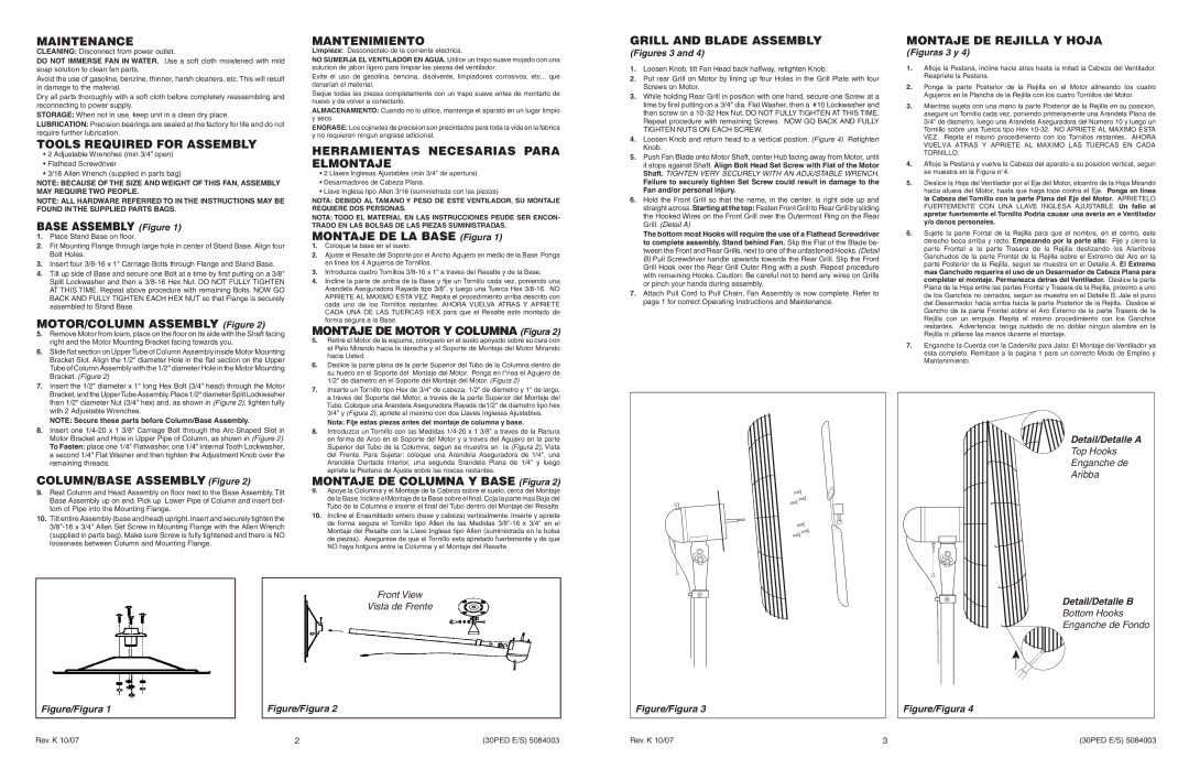
GRILL AND BLADE ASSEMBLY
(Figures 3 and 4)
1.Loosen Knob, tilt Fan Head back halfway, retighten Knob.
2.Put rear Grill on Motor by lining up four Holes in the Grill Plate with four Screws on Motor.
3.While holding Rear Grill in position with one hand, secure one Screw at a time by first putting on a 3/4" dia. Flat Washer, then a #10 Lockwasher and then screw on a
4.Loosen Knob and return head to a vertical postion. (Figure 4) Retighten Knob.
5.Push Fan Blade onto Motor Shaft, center Hub facing away from Motor, until it stops against Shaft. Align Bolt Head Set Screw with Flat of the Motor Shaft. TIGHTEN VERY SECURELY WITH AN ADJUSTABLE WRENCH.
Failure to securely tighten Set Screw could result in damage to the Fan and/or personal injury.
6.Hold the Front Grill so that the name, in the center, is right side up and straight across.Starting at the top: Fasten Front Grill to Rear Grill by sliding the Hooked Wires on the Front Grill over the Outermost Ring on the Rear Grill. (Detail A)
The bottom most Hooks will require the use of a Flathead Screwdriver to complete assembly. Stand behind Fan. Slip the Flat of the Blade be- tween the Front and Rear Grills, next to one of the unfastened Hooks. (Detail B) Pull Screwdriver handle upwards towards the Rear Grill. Slip the Front Grill Hook over the Rear Grill Outer Ring with a push. Repeat procedure with remaining Hooks. Caution: Be careful not to bend any wires on Grills or pinch your hands during assembly.
7.Attach Pull Cord to Pull Chain. Fan Assembly is now complete. Refer to page 1 for correct Operating Instructions and Maintenance.
MONTAJE DE REJILLA Y HOJA
(Figuras 3 y 4)
1.Afloje la Pestana, incline hacia atras hasta la mitad la Cabeza del Ventilador. Reapriete la Pestana.
2.Ponga la parte Posterior de la Rejilla en el Motor alineando los cuatro Agujeros en la Plancha de la Rejilla con los cuatro Tornillos del Motor.
3.Mientras sujeta con una mano la parte Posterior de la Rejilla en su posicion, asegure un Tornillo cada vez, poniendo primeramente una Arandela Plana de 3/4" de diametro, luego una Arandela Aseguradora del Numero 10 y luego un Tornillo sobre una Tuerca tipo Hex
4.Afloje la Pestana y vuelva la Cabeza del aparato a su posicion vertical, segun se muestra en la Figura n°4.
5.Deslice la Hoja del Ventilador por el Eje del Motor, elcentro de la Hoja Mirando hacia afuera del Motor, hasta que haga tope contra el Eje. Ponga en linea la Cabeza del Tornillo con la parte Plana del Eje del Motor. APRIETELO FUERTEMENTE CON UNA LLAVE INGLESA AJUSTABLE. Un fallo al apretar fuertemente el Tornillo Podria causar una averia en e Ventilador y/o danos personales.
6.Sujete la parte Fontal de la Rejilla para que el nombre, en el centro, este derecho boca arriba y recto. Empezando por la parte alta: Fije y cierre la parte Frontal a la parte Trasera de la Rejilla deslizando los Alambres Ganchudos de la parte Frontal de la Rejilla sobre el Extremo del Aro en la parte Posterior de la Rejilla, segun se muestra en el Detalle A. El Extremo mas Ganchudo requerira el uso de un Desarmador de Cabeza Plana para completar el montaje. Permanezca detras del Ventilador. Deslice la parte Plana de la Hoja entre las partes Frontal y Trasera de la Rejilla, proximo a uno de los Ganchos no cerrados, segun se muestra en el Detalle B. Jale el puno del Desarmador hacia arriba hacia la parte Posterior de la Rejilla. Deslice el Gancho de la parte Frontal sobre el Aro Externo de la parte Trasera de la Rejilla con un empuje. Repita el mismo procedimiento con los Ganchos restantes. Advertencia: tenga cuidado de no doblar ningun alambre en la Rejilla ni pillarse las manos durante el montaje.
7.Enganche la Cuerda con la Cadenilla para Jalar. El Montaje del Ventilador ya esta completo. Remitase a la pagina 1 para un correcto Modo de Empleo y Mantenimiento.
Motor Bracket and Hole in Upper Pipe of Column, as shown in (Figure 2). |
To Fasten: place one 1/4" Flatwasher, one 1/4" Internal Tooth Lockwasher, |
a second 1/4" Flat Washer and then tighten the Adjustment Knob over the |
remaining threads. |
COLUMN/BASE ASSEMBLY (Figure 2)
9.Rest Column and Head Assembly on floor next to the Base Assembly. Tilt Base Assembly up on end. Pick up Lower Pipe of Column and insert bot- tom of Pipe into the Mounting Flange.
10.Tilt entire Assembly (base and head) upright.Insert and securely tighten the
en forma de Arco en el Soporte del Motor y a traves del Agujero en la parte |
Superior del Tubo de la Columna, segun se muestra en la (Figura 2), Vista |
del Frente. Para Sujetar: coloque una Arandela Aseguradora de 1/4", una |
Arandela Dentada Interior, una segunda Srandela Plana de 1/4" y luego |
apriete la Pestana de Ajuste sobre las roscas restantes. |
MONTAJE DE COLUMNA Y BASE (Figura 2)
9.Apoye la Columna y el Montaje de la Cabeza sobre el suelo, cerca del Montaje de la Base.Incline el Montaje de la Base sobre el final.Coja la parte mas Baja del Tubo de la Columna e inserte el final del Tubo dentro del Montaje del Resalte.
10.Incline el Ensamblado entero (base y cabeza) verticalmente. Inserte y apriete de forma segura el Tornillo tipo Allen de las Medidas
Detail/Detalle A
Top Hooks Enganche de Aribba
Front View
Vista de Frente
Figure/Figura 1 | Figure/Figura 2 |
Figure/Figura 3
Detail/Detalle B
Bottom Hooks
Enganche de Fondo
Figure/Figura 4
Rev. K 10/07 | 2 | (30PED E/S) 5084003 | Rev. K 10/07 | 3 | (30PED E/S) 5084003 |