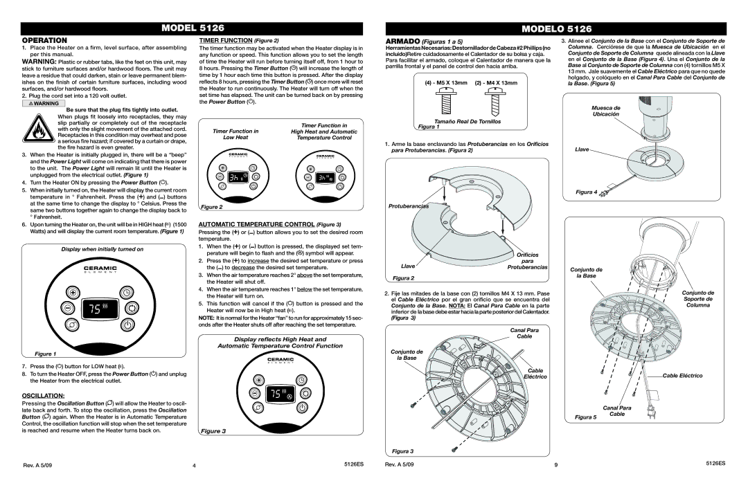
Lasko 5126 Operation, Oscillation, Timer Function Figure, Automatic Temperature Control Figure

Models: 5126

1 6
Download 6 pages 32.85 Kb
Page 4
Image 4

MODEL 5126

MODELO 5126

OPERATION

1.Place the Heater on a firm, level surface, after assembling per this manual.

WARNING: Plastic or rubber tabs, like the feet on this unit, may stick to furniture surfaces and/or hardwood floors. The unit may leave a residue that could darken, stain or leave permanent blem- ishes on the finish of certain furniture surfaces, including wood surfaces, and/or hardwood floors.

2. Plug the cord set into a 120 volt outlet.

Be sure that the plug fits tightly into outlet.

When plugs fit loosely into receptacles, they may slip partially or completely out of the receptacle with only the slight movement of the attached cord. Receptacles in this condition may overheat and pose a serious fire hazard; if covered by a curtain or drape, the fire hazard is even greater.

3.When the Heater is initially plugged in, there will be a “beep” and the Power Light will come on indicating that there is power to the unit. The Power Light will remain lit until the Heater is unplugged from the electrical outlet. (Figure 1)

4.Turn the Heater ON by pressing the Power Button ().

5.When initially turned on, the Heater will display the current room temperature in ° Fahrenheit. Press the () and ( ) buttons at the same time to change the display to ° Celsius. Press the same two buttons together again to change the display back to ° Fahrenheit.

6.Upon turning the Heater on, the unit will be in HIGH heat ( ) (1500 Watts) and will display the current room temperature. (Figure 1)

Display when initially turned on

Figure 1

7.Press the () button for LOW heat ().

8.To turn the Heater OFF, press the Power Button () and unplug the Heater from the electrical outlet.

OSCILLATION:

Pressing the Oscillation Button () will allow the Heater to oscil- late back and forth. To stop the oscillation, press the Oscillation Button () again. When the Heater is in Automatic Temperature Control, the oscillation function will stop when the set temperature is reached and resume when the Heater turns back on.

TIMER FUNCTION (Figure 2)

The timer function may be activated when the Heater display is in any function or speed. This function allows you to set the length of time the Heater will run before turning itself off, from 1 hour to 8 hours. Pressing the Timer Button () will increase the length of time by 1 hour each time this button is pressed. After the display reflects 8 hours, pressing the Timer Button () once more will reset the Heater to run continuously. The Heater will turn off when the set time has elapsed. The unit can be turned back on by pressing the Power Button ().

Timer Function in

Timer Function in

High Heat and Automatic

Low Heat

Temperature Control

Figure 2

AUTOMATIC TEMPERATURE CONTROL (Figure 3)

Pressing the () or ( ) button allows you to set the desired room temperature.

1.When the () or ( ) button is pressed, the displayed set tem- perature will begin to flash and the () symbol will appear.

2.Press the () to increase the desired set temperature or press the ( ) to decrease the desired set temperature.

3.When the air temperature reaches 2° above the set temperature, the Heater will shut off.

4.When the air temperature reaches 1° below the set temperature, the Heater will turn on.

5.This function will cancel if the () button is pressed and the Heater will now be in High heat ( ).

NOTE: It is normal for the Heater “fan” to run for approximately 15 sec- onds after the Heater shuts off after reaching the set temperature.

Display reflects High Heat and

Automatic Temperature Control Function

Figure 3

ARMADO (Figuras 1 a 5)

Herramientas Necesarias: Destornillador de Cabeza #2 Phillips (no incluido)Retire cuidadosamente el Calentador de su bolsa y caja. Para facilitar el armado, coloque el Calentador de manera que la parrilla frontal y el panel de control den hacia arriba.

(4) - M5 X 13mm (2) - M4 X 13mm

Tamaño Real De Tornillos

Figura 1

1.Arme la base enclavando las Protuberancias en los Orificios para Protuberancias. (Figura 2)

Protuberancias


Orificios

Llave

para

Protuberancias

Figura 2


2.Fije las mitades de la base con (2) tornillos M4 X 13 mm. Pase el Cable Eléctrico por el gran orificio que se encuentra del Conjunto de la Base. NOTA: El Canal Para Cable en la parte inferior de la base debe estar hacia la parte posterior del Calentador.

(Figura 3)

Canal Para

Cable

Conjunto de

la Base

Cable

Eléctrico

Figura 3

3.Alinee el Conjunto de la Base con el Conjunto de Soporte de Columna. Cerciórese de que la Muesca de Ubicación en el Conjunto de Soporte de Columna quede alineada con la Llave en el Conjunto de la Base (Figura 4). Una el Conjunto de la Base al Conjunto de Soporte de Columna con (4) tornillos M5 X 13 mm. Jale suavemente el Cable Eléctrico para que no quede holgado, y colóquelo en el Canal Para Cable del Conjunto de la Base. (Figura 5)

Muesca de

Ubicación

Llave

Figura 4

Conjunto de

la Base

Conjunto de

Soporte de

Columna

Cable Eléctrico


Canal Para

Figura 5

Cable


Rev. A 5/09

4

5126ES

Rev. A 5/09

9

5126ES

Page 4
Image 4
Lasko 5126 manual Operation, Oscillation, Timer Function Figure, Automatic Temperature Control Figure