
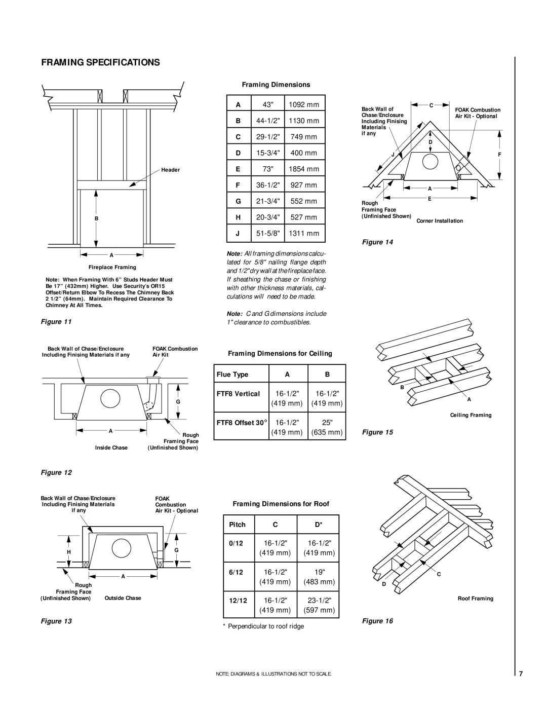
RDI-36-H, HCI-36-H specifications
The Lennox Hearth HCI-36-H and RDI-36-H represent a pinnacle of innovation and efficiency in the world of gas fireplaces. These models are highly regarded for their combination of aesthetic appeal, advanced technology, and exceptional performance, making them an excellent choice for both new constructions and retrofitting existing spaces.Starting with the HCI-36-H, this direct vent gas fireplace is designed for optimal heating while providing a stunning visual centerpiece. It features a sleek glass front that enhances the flame experience, showcasing the lifelike faux logs and glowing embers. The HCI-36-H is equipped with a powerful heat exchanger that maximizes heat output, ensuring your space remains warm and comfortable.
On the other hand, the RDI-36-H offers a more customizable experience. This model features a variety of decorative options, allowing homeowners to personalize their fireplace to fit their home’s aesthetic. From customizable front panels to decorative trim kits, the RDI-36-H is designed to cater to individual tastes while ensuring robust functionality.
Both models incorporate advanced technologies that improve energy efficiency and user experience. They utilize Lennox's patented flame technology, which creates a realistic fire while maintaining high efficiency. This technology also helps reduce emissions, making it an environmentally friendly choice. With an impressive efficiency rating, both units provide substantial warmth without excessive energy consumption.
User convenience is another significant aspect of these fireplaces. They come with an easy-to-use remote control, allowing you to adjust the flame height and heat output from the comfort of your couch. Additionally, the units offer a variety of safety features, including an automatic shut-off system that ensures peace of mind.
The HCI-36-H and RDI-36-H also boast a quick and straightforward installation process thanks to their direct vent capabilities, which minimize the need for extensive ductwork. This makes them ideal for existing living spaces, as well as new homes.
In conclusion, the Lennox Hearth HCI-36-H and RDI-36-H gas fireplaces epitomize the blend of design, technology, and efficiency. With features like customizable designs, advanced flame technology, and user-friendly operation, these models provide not just warmth, but a beautiful focal point that enhances any room. Whether you prioritize aesthetic or function, Lennox offers two exceptional options that cater to a variety of preferences.