HEARTH PRODUCTS KITS AND ACCESSORIES
750,164M REV. A 12/2008
CAST IRON FACADE KITS
LENNOX HEARTH PRODUCTS
INSTALLATION INSTRUCTIONS FOR CAST IRON FACADE KITS Model Numbers
GENERAL INFORMATION
These cast iron facade kits are designed to be used in conjunction with the grillwork kits. Together, when installed, these kits complete the front aspect of the Spectra LSS series gas fireplaces. The kits contain one of each of the following cast iron facade pieces: bottom, top, left and right piece. They also contain four 1/2 inch long
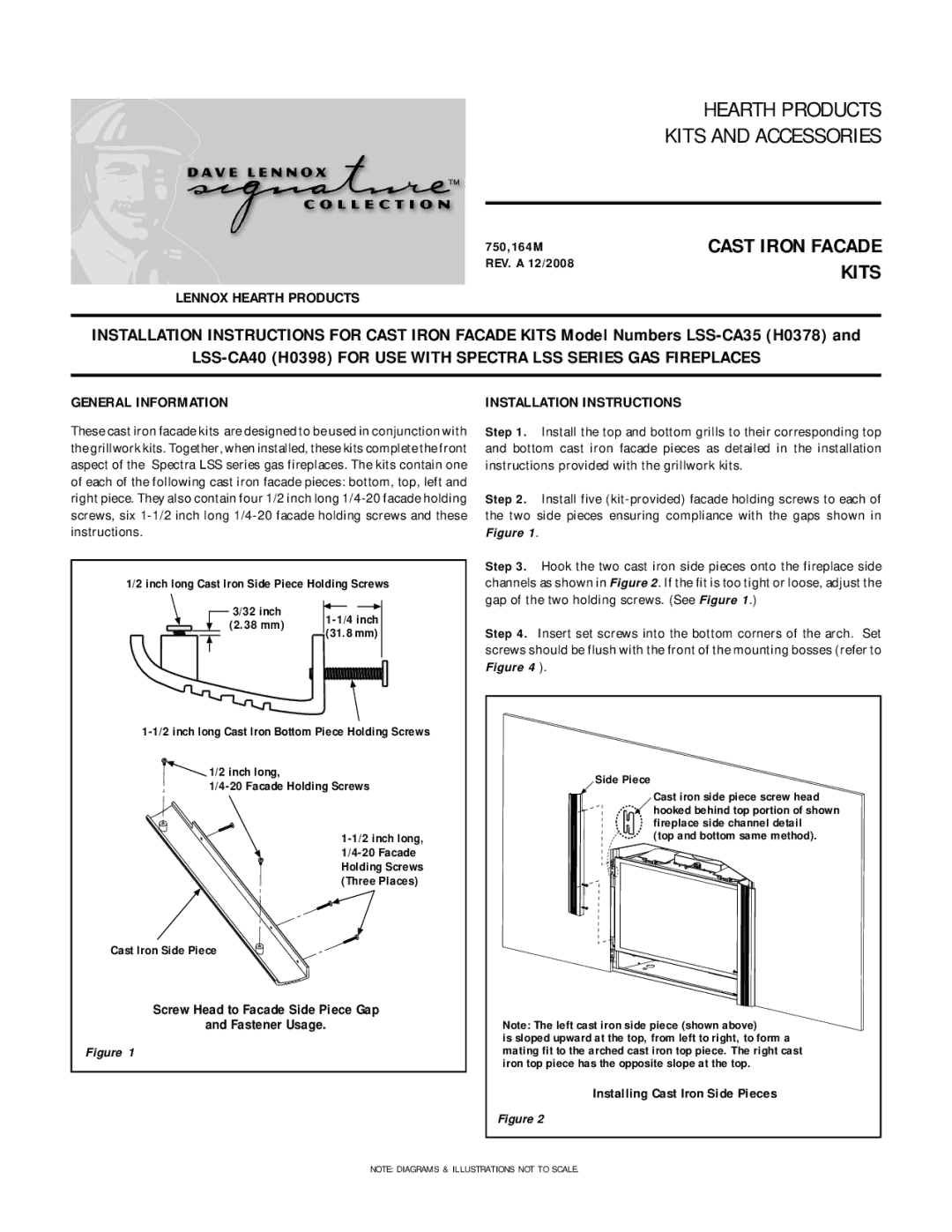
1/2 inch long Cast Iron Side Piece Holding Screws
3/32 inch
(2.38 mm)
(31.8 mm)
![]() 1/2 inch long,
1/2 inch long,
Cast Iron Side Piece
Screw Head to Facade Side Piece Gap
and Fastener Usage.
Figure 1
INSTALLATION INSTRUCTIONS
Step 1. Install the top and bottom grills to their corresponding top and bottom cast iron facade pieces as detailed in the installation instructions provided with the grillwork kits.
Step 2. Install five
Step 3. Hook the two cast iron side pieces onto the fireplace side channels as shown in Figure 2. If the fit is too tight or loose, adjust the gap of the two holding screws. (See Figure 1.)
Step 4. Insert set screws into the bottom corners of the arch. Set screws should be flush with the front of the mounting bosses (refer to Figure 4 ).
Side Piece
Cast iron side piece screw head
hooked behind top portion of shown fireplace side channel detail
(top and bottom same method).
Note: The left cast iron side piece (shown above)
is sloped upward at the top, from left to right, to form a mating fit to the arched cast iron top piece. The right cast iron top piece has the opposite slope at the top.
Installing Cast Iron Side Pieces
Figure 2
NOTE: DIAGRAMS & ILLUSTRATIONS NOT TO SCALE.