CX Power Amplifiers
Basic Operation
1. Power Switch
Disconnects power to the AC Input Connector. Set this switch to off when making or breaking connections to the amplifier.
2. AC Input Connector
The AC input connector provides power to the unit with the supplied power cord (3 conductor, 14AWG). Do not use an extension cord. For optimal performance, use an isolated power receptacle with adequate current (at least 15 Amps). Line voltages ≥10% above the specified voltage may damage the amplifier. Line voltages ≥10% below the specified voltage may cause the amplifier to enter a protection mode, indicated by the red standby LED flashing.
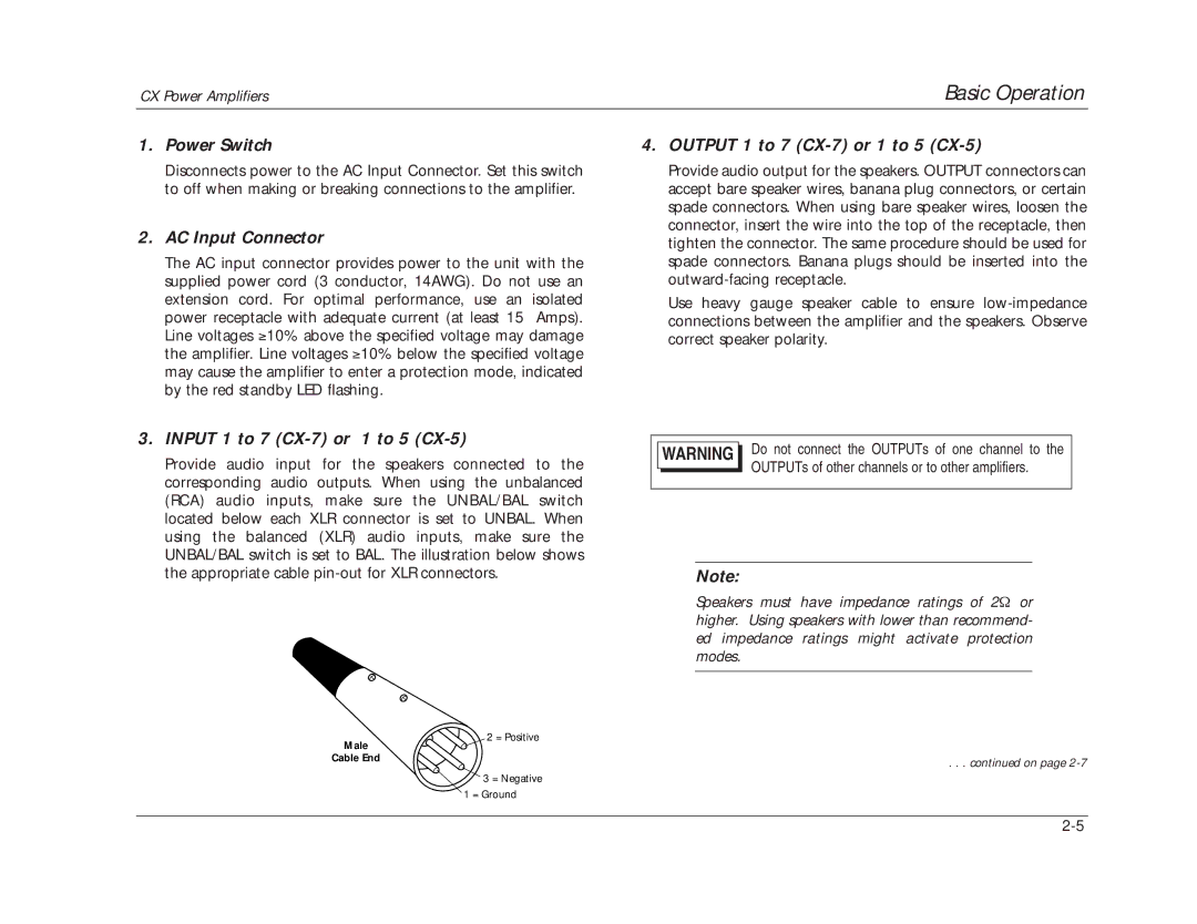
3. INPUT 1 to 7 (CX-7) or 1 to 5 (CX-5)
Provide audio input for the speakers connected to the corresponding audio outputs. When using the unbalanced (RCA) audio inputs, make sure the UNBAL/BAL switch located below each XLR connector is set to UNBAL. When using the balanced (XLR) audio inputs, make sure the UNBAL/BAL switch is set to BAL. The illustration below shows the appropriate cable
4. OUTPUT 1 to 7 (CX-7) or 1 to 5 (CX-5)
Provide audio output for the speakers. OUTPUT connectors can accept bare speaker wires, banana plug connectors, or certain spade connectors. When using bare speaker wires, loosen the connector, insert the wire into the top of the receptacle, then tighten the connector. The same procedure should be used for spade connectors. Banana plugs should be inserted into the
Use heavy gauge speaker cable to ensure
WARNING Do not connect the OUTPUTs of one channel to the OUTPUTs of other channels or to other amplifiers.
Note:
Speakers must have impedance ratings of 2Ω or higher. Using speakers with lower than recommend- ed impedance ratings might activate protection modes.
2 = Positive
Male |
|
Cable End | . . . continued on page |
|
3 = Negative
1 = Ground