*Auto-control interface and directions
(1)Adjust in the place where the influx of light like floodlight around is blocked. (illumination is less than 10 lux).
(2)Adhere closely the Color analyzer(CA210) to the module less than 10 cm distance, keep it with the surface of the Module and Color analyzer's prove vertically.(80° ~ 100°).
(3)Aging time
-After aging start, keep the power on (no suspension of power supply) and
-Using 'no signal' or 'POWER ONLY' or the others, check the back light on.
▪ Auto adjustment Map(using |
| |||||||||
|
|
|
|
|
| |||||
[CMD | ID | DATA] |
|
|
|
|
|
| ||
Wb | 00 | 00 | White Balance Start |
|
| |||||
Wb | 00 | ff | White Balance End |
|
| |||||
|
|
| CENTER |
| ||||||
|
| [CMD ID DATA] | MIN | (DEFAULT) | MAX | |||||
|
| Cool | Mid | Warm |
| Cool |
| Mid | Warm |
|
R Gain |
| jg | Ja | jd | 00 | 172 |
| 192 | 192 | 192 |
G Gain |
| jh | Jb | je | 00 | 172 |
| 192 | 192 | 192 |
B Gain |
| ji | Jc | jf | 00 | 192 |
| 192 | 172 | 192 |
R Cut |
|
|
|
|
| 64 |
| 64 | 64 | 128 |
G Cut |
|
|
|
|
| 64 |
| 64 | 64 | 128 |
B Cut |
|
|
|
|
| 64 |
| 64 | 64 | 128 |
<Caution>
Color Temperature : COOL, Medium, Warm.
One of R Gain/G Gain/ B Gain should be kept on 0xC0, and adjust other two lower than C0.(When R/G/B Gain are all C0, it is the FULL Dynamic Range of Module)
* Manual W/B process using adjust Remote control.
5. GND and HI-POT Test
5.1. HI-POT auto-check preparation
- Check the POWER cable and SIGNAL cable insertion condition
5.2.HI-POT auto-check
(1)Pallet moves in the station. (POWER CORD / AV CORD is tightly inserted)
(2)Connect the AV JACK Tester.
(3)Controller
(4)
-If Test is failed, Buzzer operates.
-If Test is passed, GOOD Lamp on and move to next proc- ess automatically.
5.3.Checkpoint
(1)Test voltage
-Touchable Metal : 3 KV / min at 100 mA
-SIGNAL : 3KV / min at 100 mA
(2)TEST time: 1 second. (case : mass production )
(3)TEST POINT
-Touchable Metal => LIVE & NEUTRAL : Touchable Metal.
-SIGNAL => LIVE & NEUTRAL : SIGNAL.
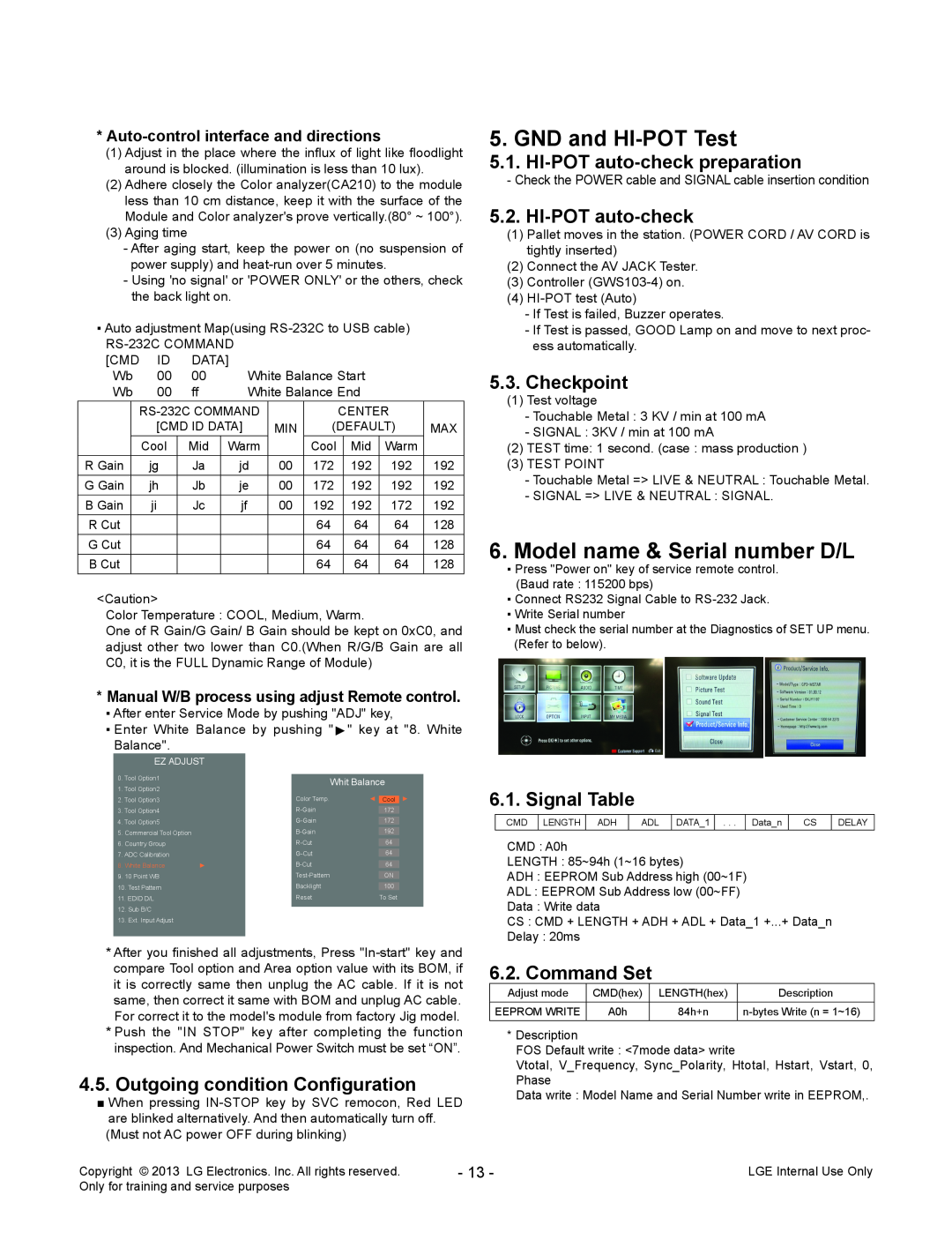
6.Model name & Serial number D/L
▪Press "Power on" key of service remote control. (Baud rate : 115200 bps)
▪Connect RS232 Signal Cable to
▪Write Serial number
▪Must check the serial number at the Diagnostics of SET UP menu. (Refer to below).
▪After enter Service Mode by pushing "ADJ" key,
▪Enter White Balance by pushing "►" key at
Balance".
EZ ADJUST
0. Tool Option1 |
|
| Whit Balance | ||
1. Tool Option2 |
|
| |||
|
|
|
| ||
2. Tool Option3 |
| Color Temp. | ◄ | Cool | |
|
|
|
| ||
3. Tool Option4 |
|
| 172 | ||
|
|
|
| ||
4. Tool Option5 |
|
| 172 | ||
|
|
|
|
|
|
5. | Commercial Tool Option |
|
| 192 | |
|
|
|
|
| |
6. | Country Group |
|
| 64 | |
|
|
|
|
| |
7. ADC Calibration |
|
| 64 | ||
|
|
|
|
| |
8. | White Balance | ► |
| 64 | |
|
|
|
|
|
|
9. | 10 Point WB |
|
| ON | |
10. Test Pattern |
| Backlight |
| 100 | |
11. EDID D/L |
| Reset |
| To Set | |
12.Sub B/C
13.Ext. Input Adjust
"8. White
►
6.1. Signal Table
CMD | LENGTH | ADH | ADL | DATA_1 | . . . | Data_n | CS | DELAY |
CMD : A0h
LENGTH : 85~94h (1~16 bytes)
ADH : EEPROM Sub Address high (00~1F)
ADL : EEPROM Sub Address low (00~FF)
Data : Write data
CS : CMD + LENGTH + ADH + ADL + Data_1 +...+ Data_n
Delay : 20ms
*After you finished all adjustments, Press
*Push the "IN STOP" key after completing the function inspection. And Mechanical Power Switch must be set “ON”.
4.5.Outgoing condition Configuration
■When pressing
6.2. Command Set
Adjust mode | CMD(hex) | LENGTH(hex) | Description |
|
|
|
|
EEPROM WRITE | A0h | 84h+n | |
|
|
|
|
*Description
FOS Default write : <7mode data> write
Vtotal, V_Frequency, Sync_Polarity, Htotal, Hstart, Vstart, 0, Phase
Data write : Model Name and Serial Number write in EEPROM,.
Copyright © | LG Electronics. Inc. All rights reserved. | - 13 - | LGE Internal Use Only |
Only for training and service purposes |
|
| |