Manuals
/
LG Electronics
/
TV and Video
/
Flat Panel Television
LG Electronics
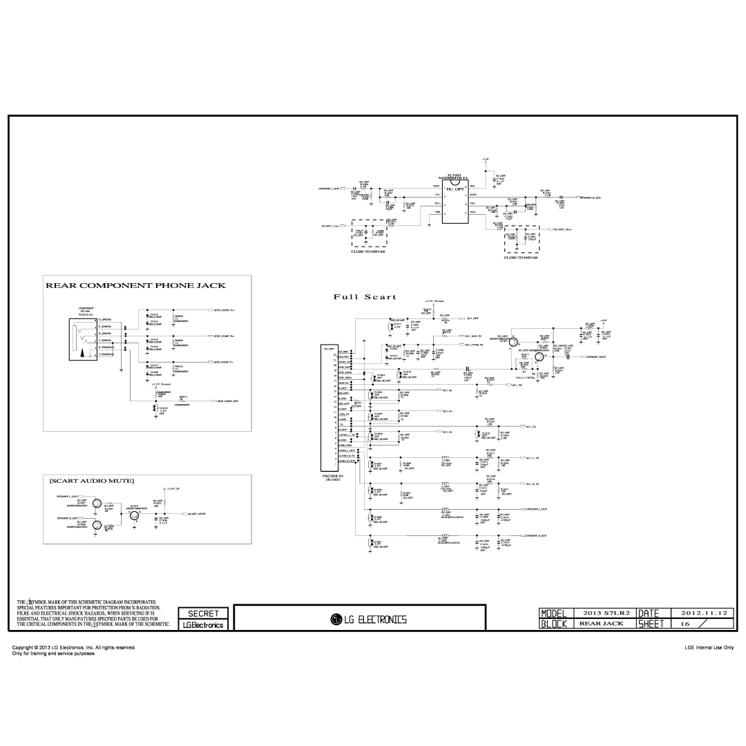
39LN549C-ZA Rear Component Phone Jack, F u l l, S c a r t, Scart Audio Mute, Euopt
Models:
39LP360H-ZA
39LN549C-ZA
39LN548C/549C-ZA
39LN548C
39LN548C/549C
1
34
38
38
Download
38 pages
48.04 Kb
31
32
33
34
35
36
37
38
Troubleshooting
Specs
Block Diagram
Signal Table
30Pin LVDS Connector
Total Assembly line process
Adjustment Instruction
IC Remove/Replacement
Safety Precautions
From Lips & Power B/D
Page 34
Image 34
Page 33
Page 35
Page 34
Image 34
Page 33
Page 35
Contents
LED TV
SERVICE MANUAL
READ THE SAFETY PRECAUTIONS IN THIS MANUAL
MODEL 39LP360H 39LN548C/549C
LG Electronics. Inc. All rights reserved
Only for training and service purposes
Copyright
LGE Internal Use Only
Before returning the receiver to the customer
SAFETY PRECAUTIONS
General Guidance
Leakage Current Cold CheckAntenna Cold Check
SERVICING PRECAUTIONS
Electrostatically Sensitive ES Devices
Small-Signal Discrete Transistor Removal/Replacement
IC Remove/Replacement
Replacement
Removal
1. Application range
SPECIFICATION
4. Model General Specification
3. Test method
Guard IntervalBitrateMbit/s
Symbolrate 4.0Msymbols/s to 7.2Msymbols/s
DVB-T
1/4, 1/8, 1/16, 1/32
5.2. RGB Input PC - HD Model
5. Video resolutions 2D
5.1. Component Input Y, CB/PB, CR/PR
5.3. RGB Input PC - FHD Model
5.3. HDMI InputPC/DTV
PCDVI
2. Designation
ADJUSTMENT INSTRUCTION
1. Application Range
3. Main PCB check process
3.2. EDID Download
After downloading, have to adjust Tool Option again
3.1. ADC Process
3.3. EDID data
4.1. White Balance adjustment
4. Total Assembly line process
3.4 Function Check
6.1. Signal Table
5. GND and HI-POT Test
6. Model name & Serial number D/L
4.5. Outgoing condition Configuration
7.1. Communication Prot connection
7. CI+ key download
6.3. Method & notice
7.2. CI+ Key Download
8.1. External speaker8OHM, 1W, Single-End
8. Check Commercial Features
8.2. IR OUT
1. Check the booting Voltage
TROUBLE SHOOTING GUIDE
2. Digital TV Video
3. Analog TV Video
4. AV Video
5. RGB Video
6. HDMI Video
9. AV Audio
10. RGB Audio
S7LR2 LGE211A-T8
BLOCK DIAGRAM
Tuner DVB- T/C
7. Audio of All iput
8. TV Audio
EXPLODED VIEW
2012 . 11
2013 S7LR2
Copyright 2013 LG Electronics. Inc. All rights reserved
VDDC
SYMBOL MARK OF THIS SCHEMETIC DIAGRAM INCORPORATES
FILRE AND ELECTRICAL SHOCK HAZARDS, WHEN SERVICING IF IS
Normal
+1.5VDDR
FROM LIPS & POWER B/D
PowerDET
+3.3VNormal780 mA
IC501
NTP-7500L
THE CRITICAL COMPONENTS IN THE SYMBOL MARK OF THE SCHEMETIC
THE SYMBOL MARK OF THIS SCHEMETIC DIAGRAM INCORPORATES
SPECIAL FEATURES IMPORTANT FOR PROTECTION FROM X-RADIATION
CONTROL IR & LED
30Pin LVDS Connector
LVDS
51Pin LVDS Connector For FHD 60Hz
FOR FHD REVERSE10bit Change in S7LR
HDMI2
HDMI EEPROM
HDMI1
For CEC
RS232C
RS - 232C
SIDE USB
HEADPHONE
RGB PC
PC AUDIO
DDR13331GHYNIX
S7LRDIVXMS10
DDR256
EAN61828901
SFLASH
S c a r t
REAR COMPONENT PHONE JACK
F u l l
SCART AUDIO MUTE
EXTSPK
EXTSPEAKERAMP
SPEAKER OUT JACK
IC1800
Option name of this page CI SLOT because of Hong Kong
CI POWER ENABLE CONTROL
CI Region
PCMCI
TU2603
GP4RGLOBALTUNERBLOCK
TU2602
TDSS-G101D
Top
Page
Image
Contents