
42PX3DCV, 42PX3DCV-UC specifications
LG Electronics has long been a key player in the world of consumer electronics, and the LG 42PX3DCV-UC is a notable example of their innovation in the plasma television market. This model is a testament to LG's commitment to delivering high-quality visual experiences while incorporating advanced technologies.One of the standout features of the LG 42PX3DCV-UC is its impressive 42-inch screen size, which provides an immersive viewing experience suitable for both casual entertainment and more serious movie nights. The plasma display technology offers exceptional picture quality, with deep black levels and vibrant colors. With a resolution of 1366 x 768 pixels, viewers can enjoy clear and detailed images, making it perfect for HD content.
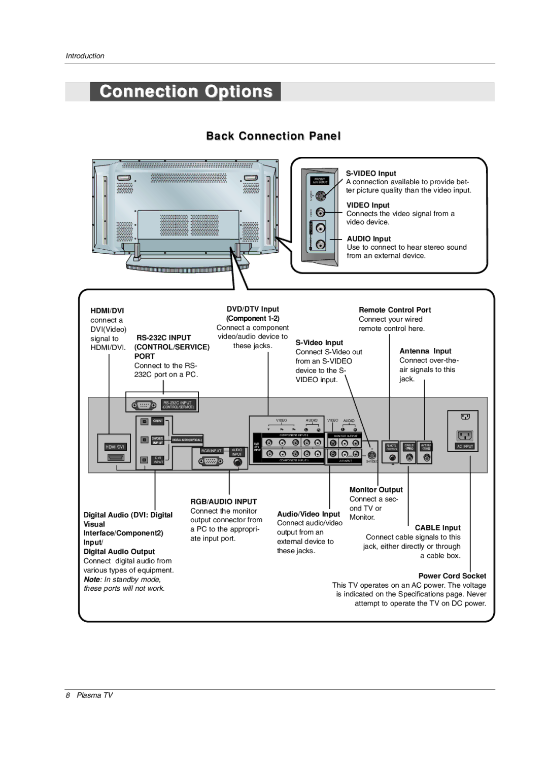
In terms of connectivity, the LG 42PX3DCV-UC includes multiple input options, such as HDMI ports, component inputs, and composite video connections. This versatility allows users to connect a variety of devices, including Blu-ray players, gaming consoles, and set-top boxes with ease. The inclusion of a built-in tuner also means that users can enjoy free-to-air broadcasts without the need for additional equipment.
The television is equipped with LG's proprietary technology to enhance the viewing experience further. One significant feature is the contrast enhancer, which improves the overall clarity and depth of the image. This technology works by adjusting the brightness and darkness levels dynamically, so viewers can appreciate every detail, even in the darkest scenes.
Another crucial characteristic of the LG 42PX3DCV-UC is its design. With a sleek and modern aesthetic, the TV can blend seamlessly into various home decors. The slim profile can save space while providing an elegant focal point in any living room.
In addition to the stunning visuals, audio quality has not been overlooked. The integrated sound system delivers decent performance, ensuring that dialogue is clear and sounds are crisp. For those seeking a more cinematic experience, the TV can easily be connected to external sound systems for enhanced audio.
Overall, the LG Electronics 42PX3DCV-UC is a well-rounded plasma television that combines impressive picture quality with user-friendly features. Its commitment to technological advancement makes it a sought-after choice for home entertainment enthusiasts looking to enhance their viewing experience. Whether it's for watching movies, playing video games, or enjoying sports, this model delivers an engaging and enjoyable experience for all users.