DISASSEMBLY INSTRUCTIONS
Important note | Chassis Assy Removal |
This set is disconnected from the power supply through the converter transformer. An isolating transformer is necessary for service operations on the primary side of the converter transformer.
Grasp both side of Frame and pull it backward smoothly.
Back Cabinet Removal
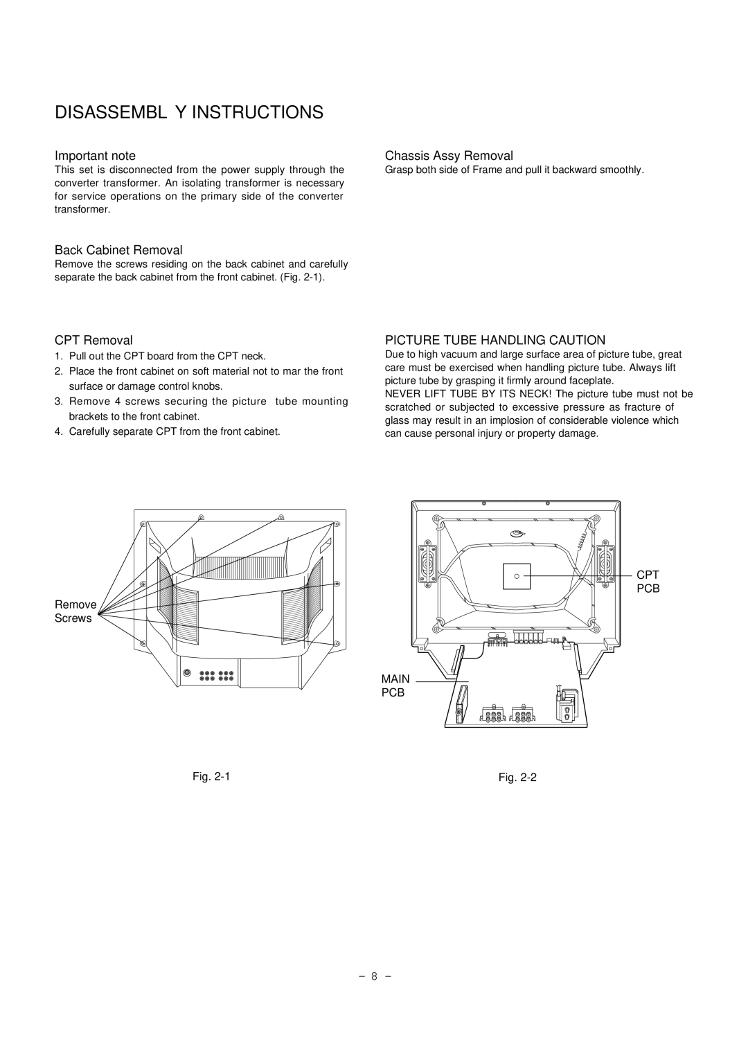
Remove the screws residing on the back cabinet and carefully separate the back cabinet from the front cabinet. (Fig.
CPT Removal
1.Pull out the CPT board from the CPT neck.
2.Place the front cabinet on soft material not to mar the front surface or damage control knobs.
3.Remove 4 screws securing the picture tube mounting brackets to the front cabinet.
4.Carefully separate CPT from the front cabinet.
Remove
Screws
Fig.
PICTURE TUBE HANDLING CAUTION
Due to high vacuum and large surface area of picture tube, great care must be exercised when handling picture tube. Always lift picture tube by grasping it firmly around faceplate.
NEVER LIFT TUBE BY ITS NECK! The picture tube must not be scratched or subjected to excessive pressure as fracture of glass may result in an implosion of considerable violence which can cause personal injury or property damage.
CPT
PCB
MAIN
PCB
Fig.
- 8 -