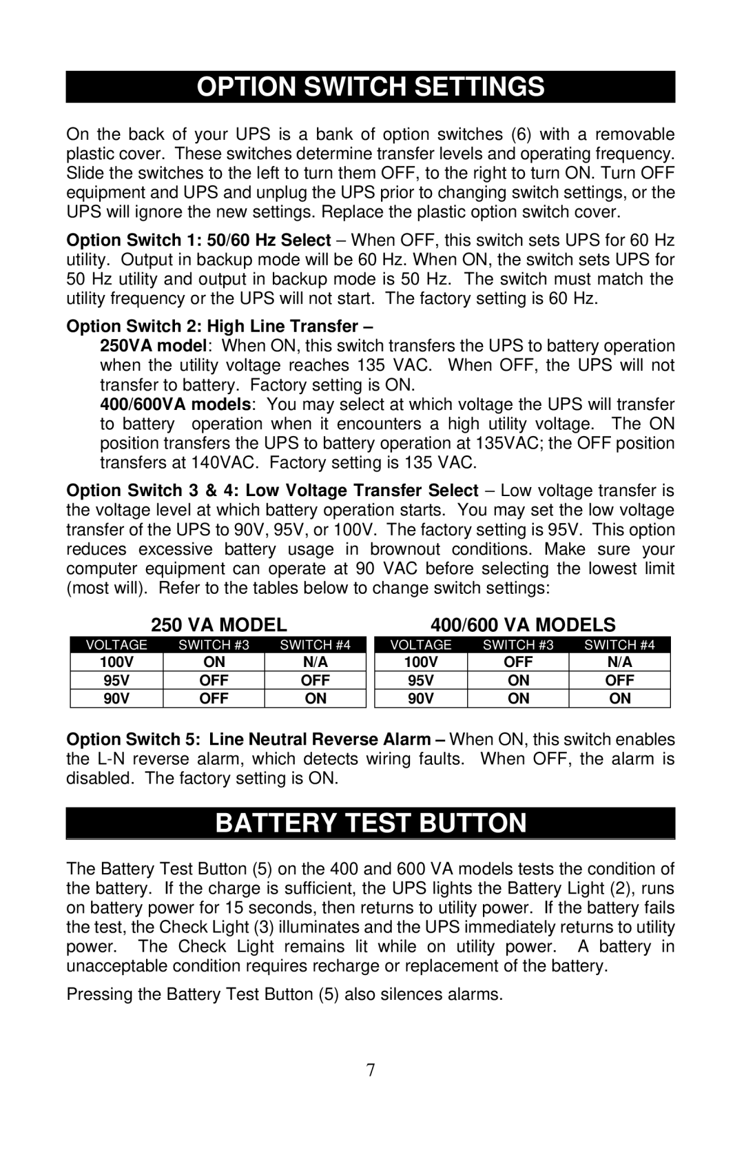
PS400-60S, PS250-60S, PS600-60S specifications
The Liebert PS600-60S, PS250-60S, and PS400-60S are advanced power supply units designed to provide reliable power protection for critical equipment. These systems are vital for industries that require an uninterrupted power supply, such as data centers, telecommunications, and healthcare.One of the standout features of the Liebert PS series is its robust design and high efficiency. The PS600-60S, with its 600VA capacity, offers a compact solution for smaller environments while still delivering reliable performance. The PS250-60S, with a 250VA capacity, caters to applications with less demanding power requirements, making it ideal for point-of-sale systems or telecommunications equipment. The PS400-60S, on the other hand, balances size and power, providing 400VA to meet moderate power needs effectively.
All models in the Liebert PS series leverage advanced technologies to ensure top-tier performance. They are equipped with sine wave output, which is crucial for sensitive electronic devices as it minimizes electrical noise and enhances performance. Additionally, the units feature automatic voltage regulation (AVR) that stabilizes output voltage, protecting equipment from surges and dips in power.
Another significant characteristic of the Liebert PS600-60S, PS250-60S, and PS400-60S is their user-friendly interface. Each model includes LED indicators that provide real-time information regarding the operational status, battery health, and load level. This feature allows users to monitor the unit easily, ensuring they can respond promptly to any potential issues.
Battery management is also a key feature in these models. They are equipped with intelligent charging technology that prolongs battery life and optimizes performance. The hot-swappable batteries allow for maintenance without disrupting the power supply, which is essential in critical environments.
In conclusion, the Liebert PS600-60S, PS250-60S, and PS400-60S power supply units are designed to offer reliable, efficient, and user-friendly solutions for power protection. Their combination of compact design, advanced technologies, and essential features makes them ideal for a vast array of applications, ensuring a stable power supply for sensitive equipment while enhancing overall operational efficiency.

