16 1/2 X
9
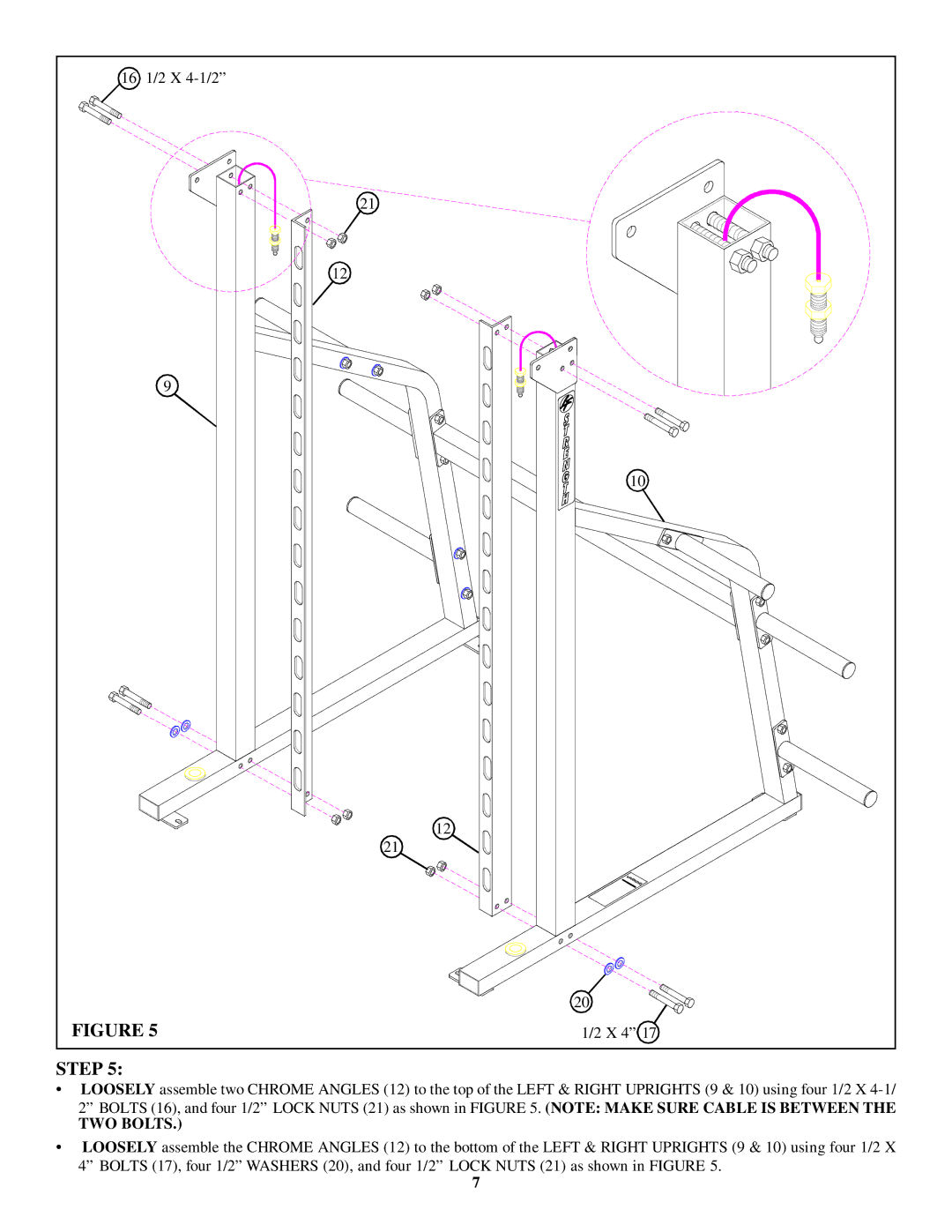
FIGURE 5
STEP 5:
21
12
12
21
10
20![]()
![]()
![]()
![]()
1/2 X 4” 17
•LOOSELY assemble two CHROME ANGLES (12) to the top of the LEFT & RIGHT UPRIGHTS (9 & 10) using four 1/2 X
2” BOLTS (16), and four 1/2” LOCK NUTS (21) as shown in FIGURE 5. (NOTE: MAKE SURE CABLE IS BETWEEN THE
TWO BOLTS.)
•LOOSELY assemble the CHROME ANGLES (12) to the bottom of the LEFT & RIGHT UPRIGHTS (9 & 10) using four 1/2 X
4” BOLTS (17), four 1/2” WASHERS (20), and four 1/2” LOCK NUTS (21) as shown in FIGURE 5.
7
