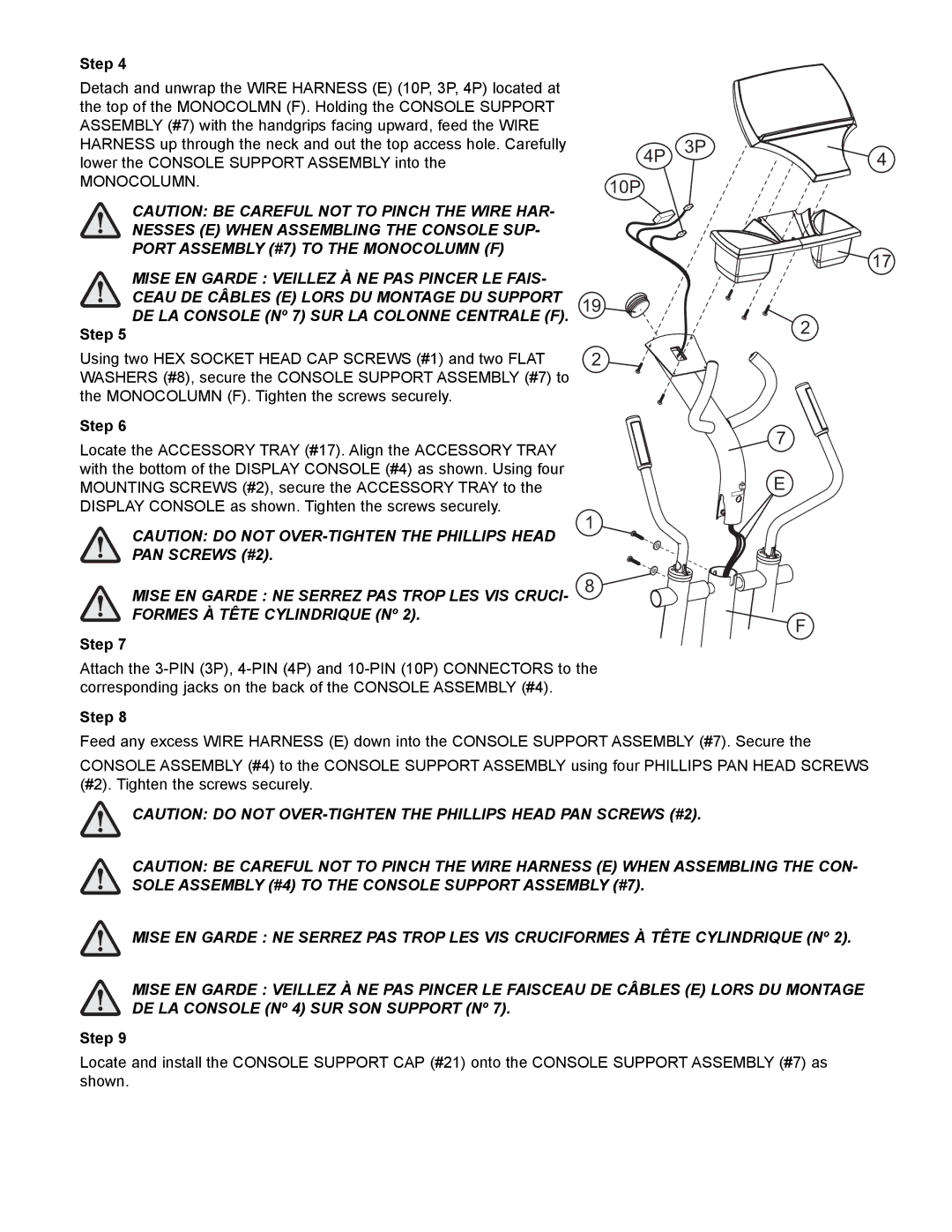
Step 4
Detach and unwrap the WIRE HARNESS (E) (10P, 3P, 4P) located at the top of the MONOCOLMN (F). Holding the CONSOLE SUPPORT ASSEMBLY (#7) with the handgrips facing upward, feed the WIRE HARNESS up through the neck and out the top access hole. Carefully lower the CONSOLE SUPPORT ASSEMBLY into the
MONOCOLUMN.
CAUTION: BE CAREFUL NOT TO PINCH THE WIRE HAR- NESSES (E) WHEN ASSEMBLING THE CONSOLE SUP- PORT ASSEMBLY (#7) TO THE MONOCOLUMN (F)
MISE EN GARDE : VEILLEZ À NE PAS PINCER LE FAIS- CEAU DE CÂBLES (E) LORS DU MONTAGE DU SUPPORT DE LA CONSOLE (Nº 7) SUR LA COLONNE CENTRALE (F).
Step 5
Using two HEX SOCKET HEAD CAP SCREWS (#1) and two FLAT WASHERS (#8), secure the CONSOLE SUPPORT ASSEMBLY (#7) to the MONOCOLUMN (F). Tighten the screws securely.
Step 6
Locate the ACCESSORY TRAY (#17). Align the ACCESSORY TRAY with the bottom of the DISPLAY CONSOLE (#4) as shown. Using four MOUNTING SCREWS (#2), secure the ACCESSORY TRAY to the DISPLAY CONSOLE as shown. Tighten the screws securely.
4P | 3P | 4 |
10P
17
19
2
2![]()
7
E
CAUTION: DO NOT
MISE EN GARDE : NE SERREZ PAS TROP LES VIS CRUCI- FORMES À TÊTE CYLINDRIQUE (Nº 2).
Step 7
1
8
F
Attach the
Step 8
Feed any excess WIRE HARNESS (E) down into the CONSOLE SUPPORT ASSEMBLY (#7). Secure the
CONSOLE ASSEMBLY (#4) to the CONSOLE SUPPORT ASSEMBLY using four PHILLIPS PAN HEAD SCREWS (#2). Tighten the screws securely.
CAUTION: DO NOT
CAUTION: BE CAREFUL NOT TO PINCH THE WIRE HARNESS (E) WHEN ASSEMBLING THE CON- SOLE ASSEMBLY (#4) TO THE CONSOLE SUPPORT ASSEMBLY (#7).
MISE EN GARDE : NE SERREZ PAS TROP LES VIS CRUCIFORMES À TÊTE CYLINDRIQUE (Nº 2).
MISE EN GARDE : VEILLEZ À NE PAS PINCER LE FAISCEAU DE CÂBLES (E) LORS DU MONTAGE DE LA CONSOLE (Nº 4) SUR SON SUPPORT (Nº 7).
Step 9
Locate and install the CONSOLE SUPPORT CAP (#21) onto the CONSOLE SUPPORT ASSEMBLY (#7) as shown.